


25
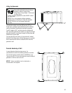
Grounding the Generator
The home generator must be installed as part of a system
that includes a listed transfer switch, with neutral to ground
bonding at the transfer switch in accordance with installation
instructions. Unless mandated by local code, additional
grounding to earth at the generator is not required. Any
grounding at generator must use metal piercing lock
washers (or equal), UL listed terminals installed per terminal
supplier’s instructions, and comply with national electrical
codes and local requirements.
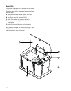
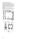
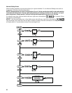
Utility Circuit Connection
i76UJMJUZwMFBETNVTUCFSPVUFEJODPOEVJU5IFi7
6UJMJUZwMFBETEFMJWFSQPXFSUPUIFHFOFSBUPSTDJSDVJUCPBSE
optional battery warmer and optional oil warmer. This power
also charges the battery. When power on these leads is lost,
the generator will start.
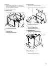
Using installer-supplied minimum 300V, 6 AWG copper
wire, or 300V, 4 AWG aluminum wire*, connect each control
circuit terminal in the generator (Utility A and Utility B) to the
fuse block in the automatic transfer switch.
*Use National Electric Code for correction factors and wire
size calculations.
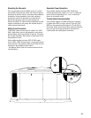
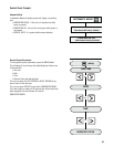
Generator Power Connection
Using installer supplied minimum 300V, 6 AWG wire,
connect generator power output Line 1, Line 2, neutral and
ground to the corresponding Line 1, Line 2, neutral and
ground in the transfer switch.
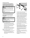
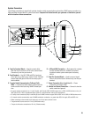
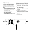
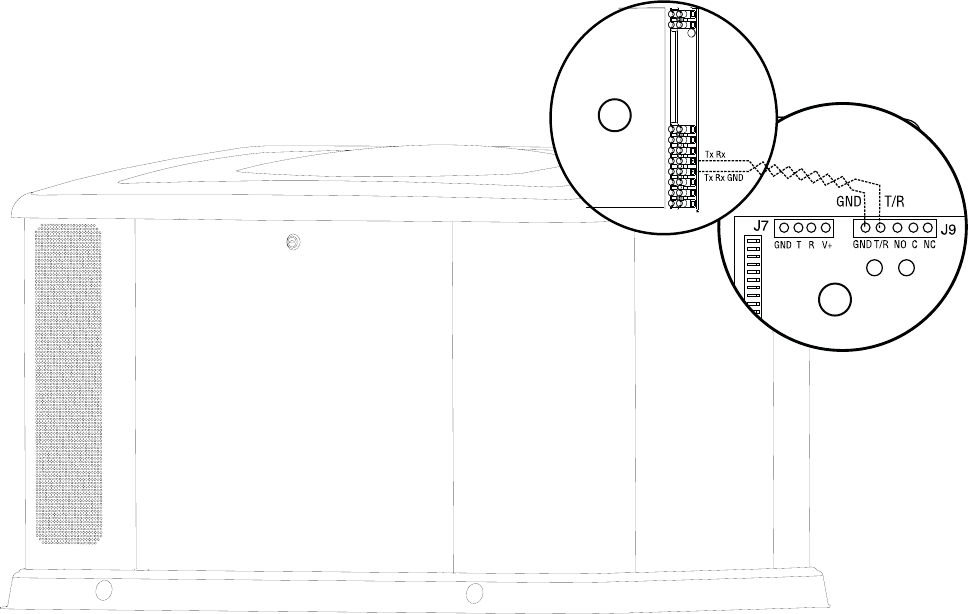
Transfer Switch Communication
Using installer supplied #18 AWG twisted pair conductors,
no greater than 200 ft in length, connect Tx Rx and Tx Rx
GND from the generator terminal block to T/R and GND on
the transfer switch control board. When making connections,
obey wire type and torque specifications printed on the
circuit breaker and neutral/ground connectors.
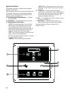
A
B