


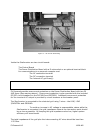

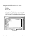
2.3.d Connecting Communications (Optional Step)
To connect the communications and load the software, follow the steps outlined below
(Refer to Figures 11 and 12):
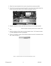
1. Hardwire the communications cable to the communication terminal, or plug in the
D-sub cable to the serial port.
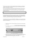
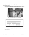
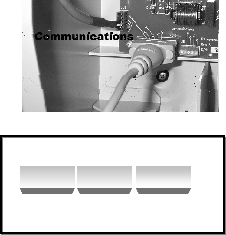
Figure 11: Communications located on the Power Distribution Board
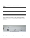
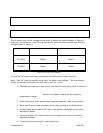
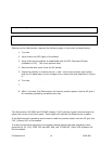
Serial Connection Table
1 7 Request to Send (RTS)
2 2 Receive Data (Rx)
3 4 Data Terminal Ready (DTR)
4 3 Transmit Data (Tx)
5 5 Signal Ground (SG)
Serial Function
Serial Cable
5 Pin Screw
Terminal
Connector
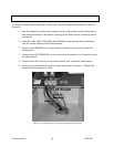
Figure 12: Hardwiring the serial connection
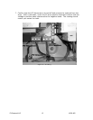
2. Replace the front cover of the StarInverter and tighten the two or four screws
located on the cover.
PV Powered LLC 13 18-28-405