


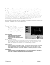


2.3.c Connecting DC Wires/PV Panels
WARNING: Before proceeding with the DC wiring, completely cover the
surface of all PV-arrays with dark material to avoid the production of electrical
current.
WARNING: Make sure the polarity and the PV panel voltage between the +
and the – cable connectors of the PV panels are correct. Then connect the
panels to the DC terminal block on the power distribution board.
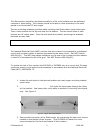
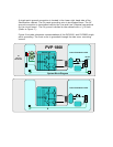
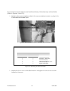
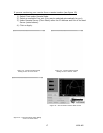
The PV panel open circuit voltage should be at or below the listed voltages in Figure 9
under all circumstances. Each DC input to the DC terminal block must be less than the
voltages listed in Figure 9.
StarInverter
Model
PV Panel Open Circuit
Voltage
DC Input to DC
Terminal Block
PVP1800 360VDC 360VDC
PVP2800 450VDC 450VDC
Figure 9: PV open circuit voltages.
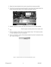
To wire the DC inputs from the PV panels to the StarInverter (refer Figure 9):
Note: Each DC input connection must carry the same input voltage. The StarInverter
allows up to three connections for both the + and the – pole.
1. Calculate the maximum open circuit (no load) for each series panel connection.
FOR ALL TEMPERATURE CONDITIONS, THE OPEN CIRCUIT VOLTAGE
FOR EACH SERIES CONNECTION MUST TOTAL LESS THAN THE OPEN
CIRCUIT VOLTAGE INDICATED IN FIGURE 9 FOR THE CORRESPONDING
STARINVERTER MODEL. Review your panel’s data sheet for operating
temperature ranges.
2. Keep track of the array positive and negative leads and mark them clearly.
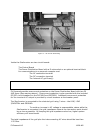
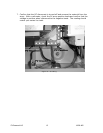
3. Route the PV array leads through the far right opening in the StarInverter.
4. Connect each series positive DC lead to the positive terminals of the power
distribution board.
5. Connect negative DC leads directly to the negative terminal on the power
distribution board.
6. Connect the ground wire(s) to the ground lug.
PV Powered LLC 11 18-28-405