


10
CHAIN SAW INFORMATION
The plastic hardware bags should include the
following:
• (2) Guidebar bolts
• (2) Guidebar nuts
• (1) Phillips self tapping screw
• (1) Saw chain
• (1) Guide bar
• (1) Hand guard
• (1) Scabbard
1. Lay chain out flat.
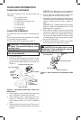
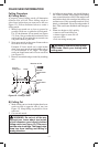
2. Install front hand guard onto saw body. Do this
b
y pressing two mounting stand-outs on hand
guard into hex-shaped holes in saw body (see
Figure 2).
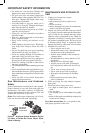
WARNING: Cutting edges on chain
are sharp. Use protective gloves when
handling chain.
IMPORTANT: Do not clamp chain saw in
vise during assembly.
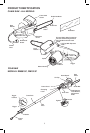
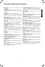
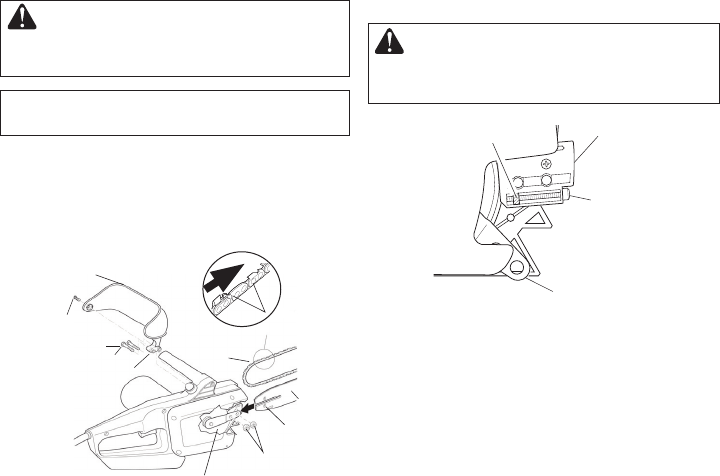
Figure 2 - Assembling Guide Bar, Chain, and
Hand Guard
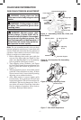
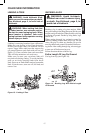
Figure 3 - Part Locations For Assembling Guide
Bar
Adjusting
Plate
Adjusting Block
Sprocket Support
Adjusting Screw
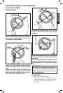
CAUTION: Do not place chain on saw
backwards. If chain is backwards, saw will
vibrate badly and will not cut.
CHAIN SAW HARDWARE
Assemble the chain saw before assembling the
pole.
Note: Some models are pre-assembled. Assembly
is not needed on these models.
See Saw Chain Tension Adjustment, page 11.
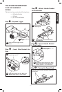
CHAIN SAW ASSEMBLY
3 Insert tapping screw through hand guard and
into saw handle. Tighten screw firmly.
4. Turn adjusting screw counterclockwise (see
Figure 3). Continue to turn adjusting screw
until adjusting block is to rear of ad
justing
plate.
5.
Install guide bar onto saw body. Place rear of
guide bar between adjusting plate and sp
rocket
support.
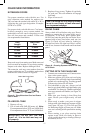
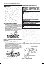
Guide Bar Nuts
Guide Bar
Bolts
Saw
Chain
Guide
Bar
Drive Sprocket
Adjusting
Hole
Mounting
Stand-Outs
Tapping
Screw
Front Hand Guard
Cutting Edge
Towards Guide Bar Nose
IMPORTANT: Make sure to insert adjusting
block into oval adjusting hole on guide bar.
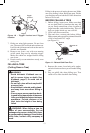
6. Line up holes on sprocket support with center
slot on guide bar and holes in saw body.
7. Insert guide bar bolts through front han
d guard,
s
aw body, center slot of guide bar, and sprocket
support. Attach guide bar nuts to guide bar
bolts.
I
MPORTANT: Tighten guide bar nuts finger
tight only. Make sure adjusting block is in oval
adjusting hole on guide bar.
8.
Place chain around drive sprocket, then along
top groove of guide bar and around guide bar
nose. Note: Make sure cutting edges of chain
are facing the right direction. Position chain
so cutting edges on t
op of guide bar face guide
bar nose (see Figure 2).
9.
Adjust saw chain tension. Follow steps under
Saw Chain Tension Adjustment, page 11.