


16
107705www.desatech.com
Replacement Chain Chain that complies with ANSI
B175.1 when used with a specific saw. It may not
meet ANSI requirements when used with other saws.
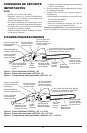
Saw Chain (Chain) Loop of chain having cutting
teeth for cutting wood. The motor drives chain. The
guide bar supports chain.
Spiked Bumper (Spike) Pointed teeth at front of
saw body beside guide bar. Keep spiked bumper in
contact with wood when felling or bucking. It helps
maintain position of saw while cutting.
Sprocket Toothed wheel that drives chain.
Switch Device that completes or interrupts electri-
cal circuit to motor of saw.
Switch Linkage This device connects switch to trig-
ger. It moves switch when you squeeze trigger.
Switch Lockout Device that reduces accidental start-
ing of saw.
Trigger Device that turns saw on and off. Squeezing
trigger turns saw on. Releasing trigger turns saw off.
Trimming (Pruning) Process of cutting limb(s) from
a living tree.
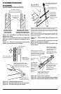
Undercut An upward cut from underside of log or
limb. This is done while in normal cutting position
and cutting with top of guide bar.
ASSEMBLY
Note:
Some models are pre-assembled. Assembly
is not needed on these models.
See Saw Chain Tension Adjustment, pages 16 and 17.
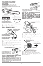
1. Lay chain out flat.
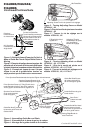
2. Loosen and remove guide bar nuts and sprocket
cover.
3. Loosen and remove drive sprocket screw or re-
move E-ring from shaft (see Figure 4). Remove
sprocket support.
4. Install guide bar onto saw body. Assemble cen-
ter slot of guide bar onto guide bar bolts.
5. To replace sprocket support, repeat step 3 in re-
verse order. Firmly tighten drive sprocket screw
with #2 Phillips screwdriver (if applicable).
6. Place chain around drive sprocket, along top
groove of guide bar, and around guide bar nose.
Note:
Make sure cutting edges of chain are fac-
WARNING: Cutting edges on chain
are sharp. Use protective gloves when
handling chain.
IMPORTANT: Do not clamp chain saw in
vise during assembly.
CAUTION: Do not place chain on
saw backwards. If chain is backwards,
saw will vibrate badly and will not cut.
CHAIN SAW NAMES AND
TERMS
Continued
ing in right direction. Position chain so cutting
edges on top of guide bar face guide bar nose (see
Figure 4, and indicator on side cover of saw).
Note:
For pre-assembled models, the saw chain ten-
sion is properly set at factory. A new chain will
stretch. Check new chain after first few minutes of
operation. Allow chain to cool down. Follow steps
below to readjust saw chain tension.
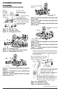
1. Before adjusting chain, make sure guide bar
nuts are only finger tight (see Figure 4). Also
make sure adjusting nib is in round adjusting hole
on guide bar (see Figures 4, 5, and 6).
SAW CHAIN TENSION
ADJUSTMENT
WARNING: Unplug chain saw from
power source before adjusting saw chain
tension.
WARNING: Cutting edges on chain
are sharp. Use protective gloves when
handling chain.
WARNING: Maintain proper chain
tension always. A loose chain will in-
crease the risk of kickback. A loose
chain may jump out of guide bar groove.
This may injure operator and damage
chain. A loose chain will cause chain,
guide bar, and sprocket to wear rapidly.
7. Insert tab of sprocket cover into slot on side cover
and rotate sprocket cover onto guide bar bolts until
sprocket cover rests against guide bar.
8. Place guide bar nuts, removed in step 2, over
guide bar bolts.
IMPORTANT:
Tighten guide bar nuts finger
tight only.
9. Turning tensioner knob (Model 107625-01, -02,
111174-01) or tensioner screw (Model 107624-01,
-02), adjust position of nib until it is aligned and in-
serted into the round adjusting hole on guide bar (see
Figures 4, 5, and 6). Turning tensioner knob or screw
counterclockwise will move tensioner bar to rear of
guide bar. Turning tensioner knob or screw clock-
wise will move tensioner bar to front of guide bar.
10. If needed, readjust guide bar nuts to finger tight only.
11. Adjust saw chain tension. Follow steps under
Saw Chain Tension Adjustment, pages 16 and 17.