


Page 15For technical questions, please call 1-888-866-5797.ITEM 61725
SAFETYOPERATIONMAINTENANCE SETUP
Reassembly
Note: Reassembly step references shown in brackets.
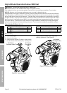
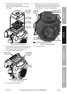
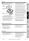
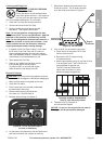
1. Replace the Outer and Inner Bowl O-rings
(137d, 137e) with the replacements
from the altitude kit. Do not reuse existing O-rings.
Carburetor
Bowl
Outer Bowl
O-ring
Inner Bowl
O-ring
Figure S: Replace Bowl O-rings
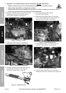
2. Assemble the Carburetor Bowl using four
Carburetor Bowl Bolts. [#25] Assemble Carburetor
Intake Elbow to Intake using Bolts. [#21]
3. Attach Solenoid Valve connector, line up green
wire with the green dot on the connector. [#20]
4. Attach Fuel Pump Bracket to front of intake
using Bolt. Gently lift the Bracket after
assembly to ensure proper alignment. [#19]
5. Attach the Choke Rod on the right side of the
Carburetor, and secure it with its Clip. [#17,18]
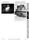
6. Attach the Breather Hose to the Carburetor,
and secure it with its Clamp. [#16]
7. Attach the Throttle Rod Spring to the Throttle Rod
Clip on the left side of the Carburetor. [#15]
8. Insert the Throttle Rod on the left side of the
Carburetor, and secure it with its Clip. [#14]
9. Attach the Fuel Hose to the port at the top of the
Carburetor and attach it using its Clamp. [#12]
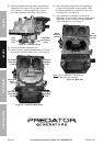
10. Install Shroud using four Shroud Bolts and two
Flange Shoulder Bolts. [#9,10] Include the Lifting
Bracket in place on the right Flange Shoulder Bolt.
11. Install Air Cleaner Base using two Air Cleaner Base
Bolts. Connect Fuel Filter Clip under left side of
Air Cleaner Base. Install the Intake Cover and
Intake Screen using the Intake Cover Bolts. [#6-8]
12. Place the Paper Air Filter, Foam Air Filter,
Air Cleaner Spacer, and Air Cleaner Top Cover
into place on the Air Cleaner Base. [#5]
13. Replace the Air Cleaner Front Cover. [#4]
14. Use the Air Cleaner Top Knob and Air Cleaner
Front Knobs to secure the Covers in place. [#3]
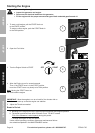
15. Once all connections are secure, open fuel valve.
16. Wipe up any spilled fuel and allow excess
to evaporate before starting engine.
To prevent FIRE, do not start the engine
while the smell of fuel hangs in the air.
Battery Setup Instructions
1. Place a fully charged, lead-acid 12 volt,
36 Ah battery (not included) in a stable,
flat location near the engine.
2. Use provided battery cables only.
3. Attach the positive cable securely to
the positive battery terminal to prevent
disconnection and short circuits.
4. Attach the negative cable securely to
the negative battery terminal to prevent
disconnection and short circuits.
5. Coat the terminals and cable ends with
a corrosion-preventive coating.
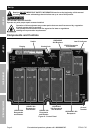
Grounding
1. The Generator must be properly grounded
in accordance with all relevant electrical
codes and standards before operation.
Have the unit grounded by a qualified electrician
if you are not qualified to do so.
2. To ground the Generator, connect a #XX AWG
grounding wire (not included) from the
Grounding Terminal on the Control Panel
to a grounding rod (not included).
The grounding rod must be an earth-driven
copper or brass rod (electrode) which can
adequately ground the Generator.
3. Refer to local regulations for
ground source information.