


Questions? Call Toll Free at 1-800-737-2112 Copyright © 2009 MAT Engine Technologies, LLC
Read and follow the assembly instructions. Do not discard any parts or materials until the unit is assembled.
References to the right or left side of the blower are from the viewpoint of the operator’s position behind the blower.
Assembly
• Save all instructions
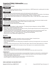
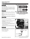
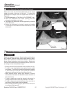
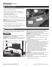
NOTE: There are two positions in which the handle can be
attached – a high position and a low position. (See Figure 2)
1. Assemble the handle tabs into the holes on the lower
frame tubing. Use the bottom holes for the low handle
position. Use the middle holes for the high handle
position. (See Figure 2)
2. Secure the handle onto the frame tubing with the (2) pipe
bolts and the (2) plastic wing nuts. Firmly hand-tighten
the wing nuts. (See Figure 2)
WARNING
Do not operate blower if it is damaged or not completely and correctly assembled.
WARNING
Before doing any assembly or maintenance to the unit, remove the wire from the spark plug.
WARNING
Always wear ANSI compliant safety glasses with side shields while assembling the blower.
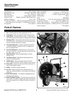
The following components will be found in the carton.
Quantities shown in ( ).
1. (1) Walk Behind Blower
2. (1) Blower Operator’s Manual
3. (1) Handle
4. (1) Front Flow Attachment (stored under the frame)
5. (1) Bottle of SAE 30 Engine Oil
6. (1) Parts bag containing the following:
(2) Plastic Wing Nuts (M8)
(2) M8x35mm Pipe Bolts
(1) Spark plug socket wrench w/ rod
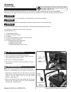
1. Remove all parts and packaging components.
2. Use a utility knife to cut all 4 vertical edges and lay the
side panels flat around the blower.
3. Remove any remaining packaging.
4. Roll the unit out from the carton, and place on a hard
level surface.
How to Remove Blower from Carton
A
How to Assemble the Handle
B
If you need assistance or find any parts missing, CALL
TOLL FREE: 1-800-737-2112.
6
Upper
Tube Hole
Frame Tubing
Pipe Bolt
Plastic
Wing Nut
Middle
Tube Hole
Handle
Bottom
Tube Hole
Handle Tab
Figure 2