


Questions? Call Toll Free at 1-800-737-2112 Copyright © 2009 MAT Engine Technologies, LLC
Operation (Continued)
• Save all instructions
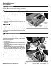
How to Stop the Blower
C
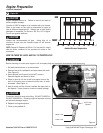
Move the ON/OFF Switch to the OFF position. (See gure 6)
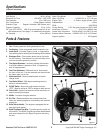
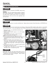
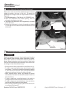
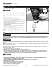
How to Adjust the Vertical Flow Angle
D
The vertical air flow direction can be adjusted between
3 positions: Straight (level), 15 degrees upward, and 15
degrees downward. Refer to Figure 8 when performing the
adjustment steps below:
1. Stop the engine.
2. Pull the index lever out of its existing hole.
3. Rotate the index lever to the desired position.
4. Release the index lever and allow it to insert into the
desired hole.
WARNING
Never adjust the flow angle when engine is running. Never
stand or put your hand in front of the discharge opening
when the engine is running. Never put hands, fingers, or
anything else inside the discharge opening when the engine
is running. There are rotating blades inside which can cause
serious injury.
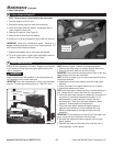
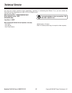
How to Redirect Air Flow toward the Front
E
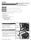
A Front Flow Attachment is included with your blower. Assembling this attachment to the blower will cause the air flow to
be redirected to the front of the blower.
Adjustment
Lever
Level
15° Upward
Air Flow
Louver
10
To assemble this attachment to the blower, follow the steps
below and refer to Figure 9:
1. Stop the engine.
2. Rotate the vertical adjustment lever to the level position
(See Figure 8)
3. Loosen the attachment knob located on top of the blower
discharge chute
4. Orient the attachment so the “This Side Up For USE” is up.
5. Slide the front flow attachment over the discharge
chute with the orientation identified on the label. The slot
on the top of the front flow attachment will mate
with the bolt of the attachment knob.
6. Hand-tighten the attachment knob to secure the
attachment.
Note: when properly assembled, the attachment knob will fit
inside of the round emboss on the top of the attachment.
15° Downward
Discharge
Chute
Bolt
Round
Emboss
Slot
Attachment
Knob
Front Flow
Attachment
Figure 8
Figure 9