


Questions? Call Toll Free at 1-800-737-2112 Copyright © 2009 MAT Engine Technologies, LLC
8
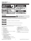
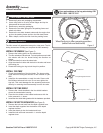
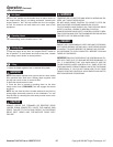
1. Remove all parts and packaging components.
2. Use a utility knife to cut all 4 vertical edges and lay the
side panels flat around the tiller.
3. Remove any remaining packaging.
4. Remove the two bolts going thru the packing frame and
wheel axle holes.
5. Remove the two bolts located underneath the engine that
go thru the packing frame and thru the tiller base frame.
6. With a helper, remove the tiller from the packing frame.
How to Remove Tiller from Carton
A
Assembly Instructions
B
Assembly (Continued)
• Save all instructions
If you need assistance or find any parts missing, CALL
TOLL FREE: 1-800-737-2112.
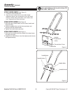
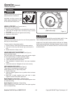
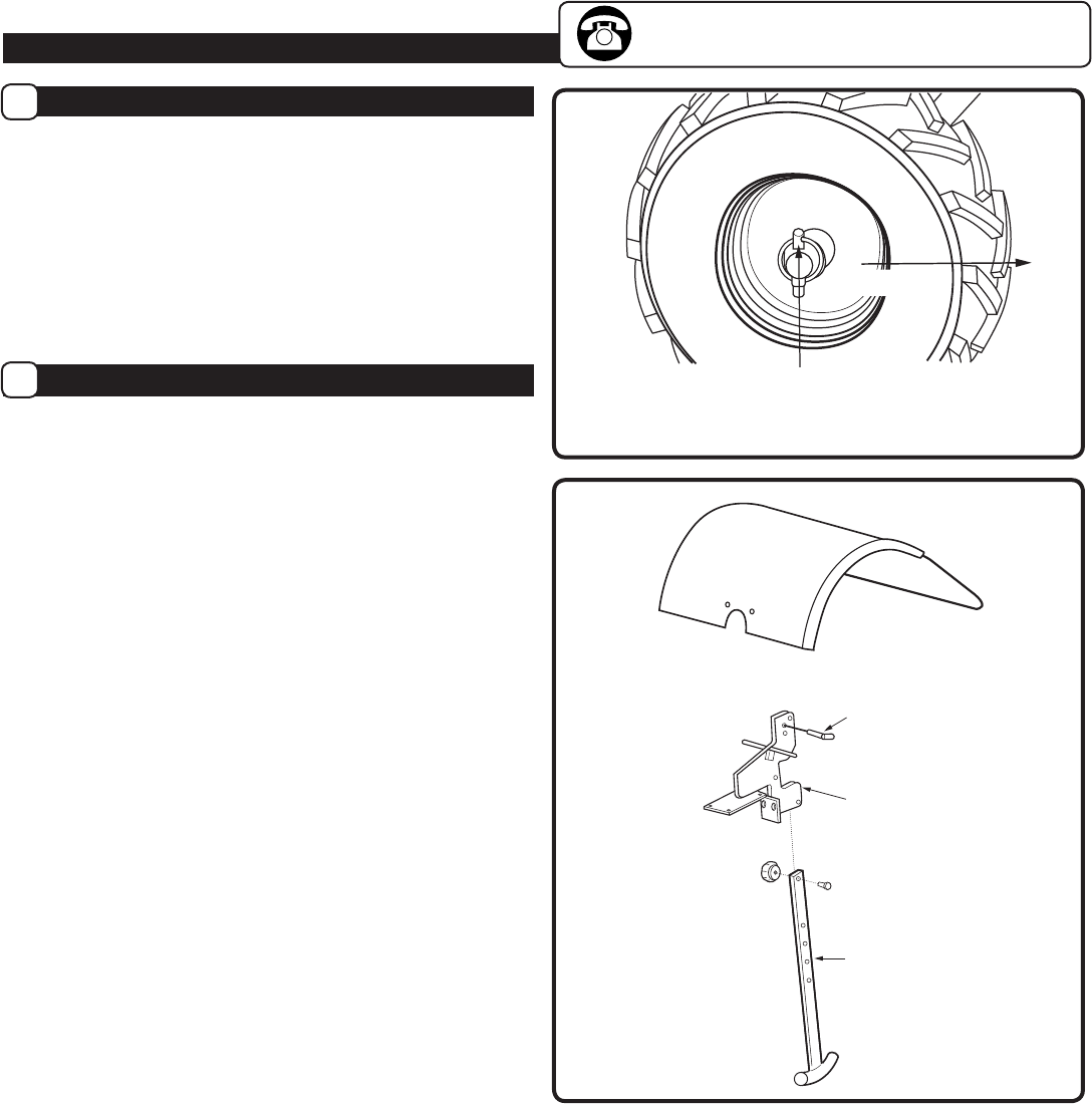
Dentent Pin
Depth Regulator Bracket
Depth Regulator Lever
Figure 3
The tiller comes fully assembled except for a few parts. The fol-
lowing instructions will help you complete the tiller assembly.
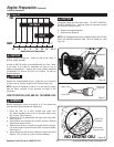
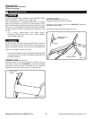
INSTALL THE WHEELS (See Figure 2)
1. Remove the locking pins from the wheel hubs.
2. The tiller wheels are directional. For best performance install
the wheels with the tire thread facing the direction as
shown.
3. Slide the wheel hub onto the wheel axle.
4. Align the wheel hub hole with the hole in the axle and insert
the locking pin.
5. Rotate the locking pin ring to lock the pin in position.
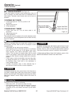
INSTALL THE TINES
1. Check the orientation of the tine blade. The sharp cutting
edge should be facing the direction of tine rotation for your
tiller.
2. Install the tine assemblies on each tine axle. Secure with
M10x50mm bolts and lock nuts. Do not over tighten the
tine bolt. This could damage the tine assembly and cause
difficulty in removing the tine assembly from the tine axle.
INSTALL THE TINE SHIELD
1. Remove the 4 bolts installed in the tine shield brackets
above the transmission housing.
2. Place the tine shield on the bracket and secure with the
bolts removed in 1. above.
3. Install the tine shield side guards with the hardware provided.
INSTALL THE DEPTH REGULATOR (See Figure 3)
1. Remove the bolt and knob from the depth regulator lever.
2. Insert the depth regulator into the bottom of the depth
regulator bracket.
3. Insert the detent pin thru the bracket and lever.
4. Install the bolt and knob removed in 1. onto the depth
regulator lever.
Wheel lock pin in tiller operating position
(wheel hub and axle holes)
FRONT
Figure 2