


Questions? Call Toll Free at 1-800-737-2112 Copyright © 2009 MAT Engine Technologies, LLC
14
Adjustments
H
Operation (Continued)
• Save all instructions
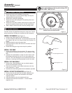
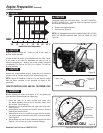
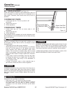
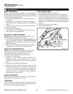
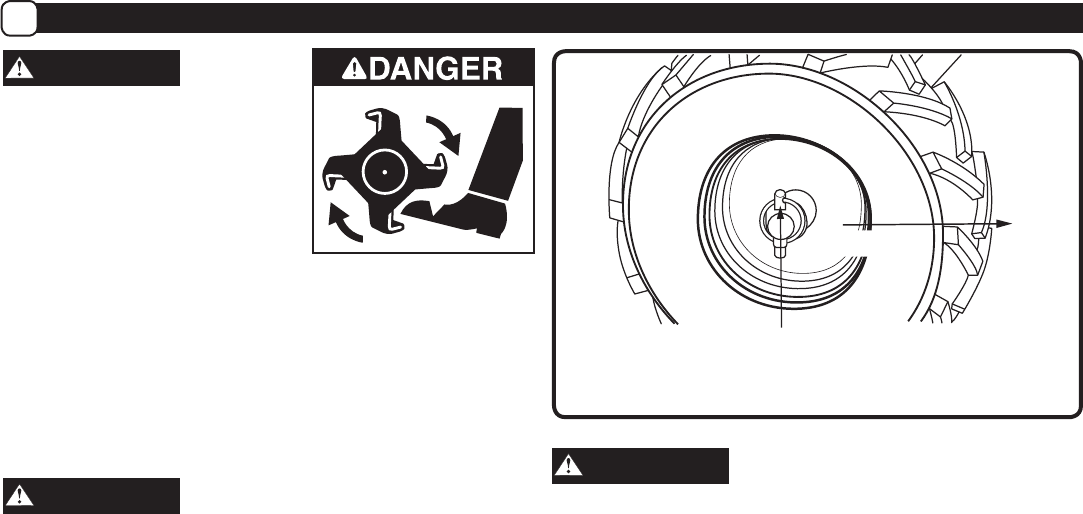
WHEEL LOCK PINS (See Figures 2 and 11)
Place wheels in tilling position.
1. Remove lock pin. Align hole in axle with hole in wheel hub.
2. Insert lock pin through holes, fold lock pin ring to secure
pin to axle.
3. Firmly lock wheel and axle together before tilling.
4. Repeat for other wheel.
WARNING
Always have both wheel lock pins in or out. Do not operate tiller
with only one wheel locked.
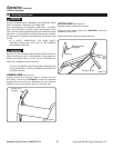
To place wheels in free-wheel position.
1. Remove lock pin. Slide wheel inward toward machine.
2. Insert pin in axle only, fold lock pin ring to secure pin to
axle.
3. Wheel should turn freely on axle.
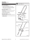
HANDLEBAR HEIGHT ADJUSTMENT (See Figure 4)
Adjust handlebar height.
The ideal height of the handlebar varies with operator height
and the depth of tilling. To adjust handlebar height:
1. Unscrew nuts and remove top bolts on each side.
2. Loosen the lower bolts. Do not remove.
3. Align handlebar to desired holes on the lower handlebar
mount.
4. Install bolts and nuts. Retighten all four bolts securely.
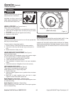
DEPTH REGULATOR LEVER (See Figure 3)
Tilling depth is controlled by the height of the
depth regulator lever. To adjust tilling depth:
1. Remove detent pin.
2. Raise the depth regulator lever to position tines at chosen
tilling depth.
3. Align hole in depth regulator lever with hole in depth
regulator bracket and replace detent pin.
Depth Regulator Lever Down = Shallower tilling.
Place the detent pin in the top hole of the depth regulator lever
for shallowest tilling.
Depth Regulator Lever Up = Deeper tilling.
Place the detent pin in the bottom hole of the depth regulator
lever for deepest tilling.
WARNING
ADJUSTING ANY CONTROLS.
Wheel lock pin in free-wheel position
(axle holes only)
FRONT
Figure 11
WARNING
-
TROL LEVERS ARE RELEASED TO NEUTRAL POSITION.
-
-
ULATOR LEVER.