


6
ASSEMBLY INFORMATION --
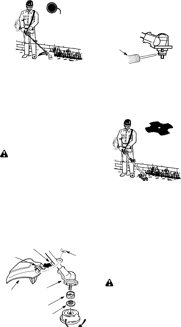
TRIMMER HEAD
TRIMMER
HEAD
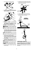
NOTE:
Removetheblade andmetalshieldbe-
fore attaching the plastic shield and trimm er
head. To remove blade, align hole in the dust
cup with the hole in the side of the gearbox by
rotating the blade. Insert a small screwdriver
into aligned holes. Thisw illkeeptheshaftfrom
turning while loosening the blade nut. Remove
blade nut by turning clockwise. Remove the
screw driver. R emove both washers and blade.
Toremove metal shield, loosen and removethe
four mounting scr ew s. See ATTACHING THE
METAL SHIELD and INST ALLATION OF THE
METALBLAD Efo rillustratio ns. B esuretostor e
all parts and i nstructions for future use.
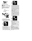
ATTACHING THE PLASTIC SHIELD
AND TRIMMER HEAD
WARNING:
The shield mustbeprop-
erly installed. The shield provides partial
protection to the operator and others from the
risk of thrown objects, and is equipped with a
line limiter blade which cuts excess line tothe
proper length. The l ine limiter blade (on un-
derside of shield) is sharp and can cut you.
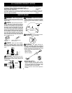
1. Remove wing nut from shield.
2. Insert bracket into slot on shield.
3. Pivot shield until boltpasses through hole
in bracket.
4. Tighten the wing nut securely.
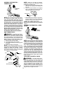
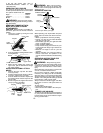
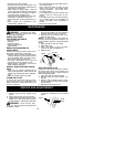
NOTE:
If your unit has a plastic cover over
the threads on thethreaded shaft, removethe
covering to expose the threads. Before
installing the trimmer head, make sure the
dust cup and retaining washer are positioned
on the gearbox as shown below.
Wing Nut
Retaining Washer
Dust Cup
Bracket
Slot
Shield
Gearbox
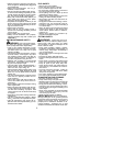
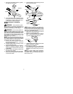
NOTE:
Make sure all parts are properly
installed as s hown in the illustration before
installing the trimmer head.
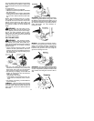
5. Align hole in the dust cup with the hole in
the side of the gearbox by rotating the
dust cup.
6. Insert a small screwdriver into aligned
holes. This will keep the shaft from turn-
ing while tightening trimmer head.
Screwdriver
7. While holding the screwdriver in position,
thread trimmer head onto the shaft in the
direction shown on the decal (counter-
clockwise). Tighten until secure.
NOTE:
The retaining washer must be posi-
tioned with the raised section facing tow ar d the
gearbox.
ASSEMBLY INFORMATION -- WEED
BLADE
WEED
BLADE
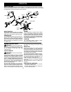
NOTE:
Remove the tr immerhead and plastic
shield before attaching the metal shield and
installing the weed blade. To rem ove the trim-
merhead,alignholeinthedust cupw iththehole
in the side of the gearbox by rotating the dust
cup. Insert a small screwdriver into aligned
holes. T hiswill keepthe shaftfromturningwhile
loosening the trimmer head. Remove the trim-
mer head by t urning c lockw ise. Remove the
screw driver. To remove the plastic shield, loos-
enand removewingnut. Pivotshield torelease
bracket from slot. See INSTALLATION OF
THECUTTINGHEADand ATTACHINGTHE
PLASTIC SHIELD forillustrations. Besureto
store all parts and instructions for future use.
Never use the trimmer head with the metal
blade installed.
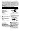
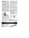
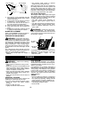
ATTACHING THE METAL SHIELD
WARNING:
The metal shield must
be properly installed on the tool anytime the
tool is usedwithablade. The forward tip ofthe
metal shield helps to reduce the occurrence
of blade thrust which can cause seriousinjury
such as amputation to the operator or by-
standers. Failure to install the shield in the
position shown can result in serious injury to
the operator. The length of the shield m ust be
aligned with the l ength of the tube.