


4
age inotherwise healthy people. If symptoms
occur such as numbness, pain, loss of
strength, change in skin color or texture, or
loss of feeling in the fingers, hands, or joints,
discontinue the use ofthis tool andseekmed-
ical attention. An anti --vibration system does
not guarantee the a voidance of these prob-
lems. Users who operate power tools on a
continual and regular basis must monitor
closely their physical condition and thecondi-
tion of this tool.
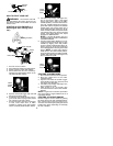
SPECIAL NOTICE:
This unit is equipped
with a temperature l imiting muffler and spark
arresting screen which meets the require-
ments of California Codes 4442 and4443. All
U.S. forest land and the states of C alifornia,
Idaho, Maine, Minnesota, New Jersey, Ore-
gon, and Washington require by law that
many internal combustion engines be
equipped withasparkarresting screen. Ifyou
operate inalocale wheresuch regulations ex-
ist, you arelegally responsible formaintaining
the operating condition of theseparts. Failure
to do so is a violation of the law. For normal
homeowner use,the mufflerand sparkarrest-
ing screen will not require any service. After
50 hours of use, we recommend that your
mufflerbeservicedorreplaced by yourautho-
rized service dealer.
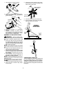
ASSEMBLY
CARTON CONTENTS
Check carton contents against the f ollowing
list:
S
Powerhead
S
Brushcutter attachment
S
Blade shield screws (4)
S
Cupped washer
S
Large nut for installing blades
S
Hex wrench
S
Metal shield
S
Plastic shield
S
Shoulder strap with warning
S
4--point weed blade
S
Trimmer head (assembled on unit)
S
Handlebar (assembled on unit)
S
Wing nut (screwed onto shield)
S
Container of oil
WARNING:
Always stopunit and dis-
connect spark plug before performing anyas-
sembly procedures.
WARNING:
If received assembled,
repeat all steps to ensure your unit is properly
assembled and all f asteners are secure.
Examine parts for damage. Do not use dam-
aged part s.
NOTE:
If you need assistance or find parts
missing or damaged, call 1-800-554-6723.
It is norm al for the fuel filter to rattle in the
empty fuel tank.
Finding fuel or oil residue on muffler isnormal
due to carburetor adjustments and testing
done by the m anufacturer.
TOOLS REQUIRED
S
Hex wrench (provided)
S
Adjustable wrench
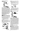
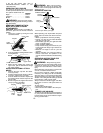
INSTALLING BRUSHCUTTER
ATTACHMENT
CAUTION:
When installing brushcutter at-
tachment, place the unit on a flat surface for
stability.
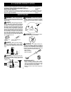
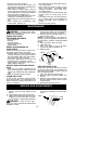
1. Loosen the coupler by turning the knob
counterclockwise.
Coupler
Knob
LOOSEN
TIGHTEN
Shipping
protector
2. Remove shipping protector from coupler.
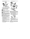
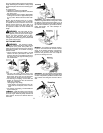
3. R emove the tube cap from the brushcutter
attachment (if p r esent).
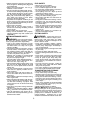
4. Position locking/release button of attach-
ment into guide recess of coupler.
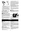
5. Push theattachment intothe coupleruntil
the locking/release button snaps into the
primary hole.
6. Before using the unit, tighten the knob se -
cur e ly by turning clockwise.
Coupler Primary Hole
Upper
Tube
Locking/
Release
Button
Lower
Attachment
Guide Recess
WARNING:
Make sure the locking/
release button is locked i n the primary hole
and the knob is securely tightened before op-
erating the unit. Allattachments aredesigned
to be used in the primary hole.
For opt ional attachments, see the AS-
SEMBLY section of the applicable attach-
ment i nstruction manual.
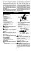
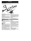
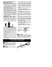
ADJUST AND SECURE THE HAN-
DLEBAR
DANGER:
Toavoidserious injury,the
barrier portion of the handlebar must be ad-
justed and remain installed as shown to pro-
vide a barrier between operator and the spin-
ning blade. The handlebar clamp must be
positioned between the arrowsonthehandle-
bar decal.