


5
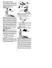
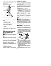
CONFIGURING YOUR UNIT
You can configure your unit using a cutting
head for grass and light weeds, or a weed
blade for cutting grass, weeds, and brush up
to 1/2inch indiameter. Toas semble yourunit,
go to the section for the desired configuration
and follow the instructions.
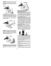
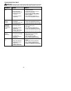
ASSEMBLY INFORMATION --
TRIMMER HEAD
TRIMMER
HEAD
NOTE:
Removetheblade andmetalshieldbe-
fore attaching the plastic shield and trimm er
head. To remove blade, push in locking lever
and hol d. R otate bladenutuntilthe lockinglever
falls into one of the grooves in the dust cup.
Continuetoholdthelockinglever. This willkeep
the shaft from turning while loosening the blade
nut. Rem ove blade nut by turning clockwise.
Release locking lever. Remove both washers
and blade. To r emove metal shield, loosen and
remove the four mounting screws. See A T-
TACH ING TH E METAL SHIELD and INSTAL-
LATION OF THE M ETAL BLAD E for illustra-
tions. Be sur e to storeall parts and instructions
for future use.
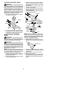
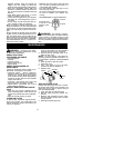
ATTACHING THE PLASTIC SHIELD
AND TRIMMER HEAD
WARNING:
The shield mustbeprop-
erly installed. The shield provides partial
protection to the operator andothers fromthe
risk of thrown objects, and is equipped with a
line limiter blade which cuts excess line tothe
proper length. The l ine limiter blade (on un-
derside of shield) is sharp and can cut you.
1. Remove wing nut from shield.
2. Insert bracket into slot on shield.
3. Pivot shield until bolt passes through hole
in bracket.
4. Tighten the wing nut securely.
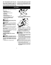
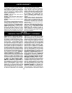
NOTE:
If your unit has a plastic cover over
the threads on thethreaded shaft, removethe
covering to expose the threads. Before
installing the trimmer head, make sure the
dust cup and retaining washer are positioned
on the gearbox as shown below.
Wing Nut
Dust Cup
Bracket
Slot
Shield
Gearbox
Retaining Washer
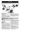
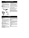
NOTE:
Make sure all parts are properly
installed as s hown in the illustration before
installing the trimmer head.
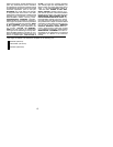
5. Push in locking lever and hold.
6. Rotate dust cup until the locking lever
falls into one of the grooves
.
Locking Lever
7. Continue to hold inlocking lever. This will
keep the shaft from turning while tighten-
ing the trimmer head.
8. Threadtrimmer head onto the shaft inthe
direction shown onthe decal. Tighten un-
til secure.
9. Release locking lever.
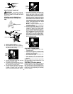
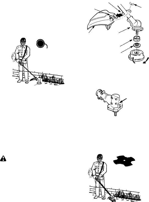
ASSEMBLY INFORMATION -- WEED
BLADE
WEED
BLADE
NOTE:
Remove the trimmer head and plas-
tic shield before attaching the metal shield
and installing the weed blade. To remove the
trimmer head, push in locking lever and hold.
Rotate trimmer head until the locking lever
falls into one of the grooves in the dust cup.
Continue to hold in locking lever. This will
keep the shaft from turning while l oosening
the cutting head. Toremove the plastic shield,
loosen and remove wing nut. Pivot shield to
release bracket from slot. See INSTALLA-
TION OF THE CUTTING HEAD and AT-
TACHINGTHEPLASTICSHIELD forillustra-
tions. Be sure to store all parts and
instructions for future use. Never use the
trimmer head with the metal blade installed.