


4
Idaho, Maine, Minnesota, New Jersey, Ore-
gon, and Washington require by law that
many internal combustion engines be
equipped withasparkarresting screen. Ifyou
operate inalocale wheresuch regulations ex-
ist, you arelegally responsible formaintaining
the operating condition of these parts. Failure
to do so is a violation of the law. For normal
homeowner use,the mufflerand sparkarrest-
ing screen will not require any service. After
50 hours of use, we recommend that your
mufflerbeservicedorreplaced by yourautho-
rized service dealer.
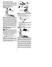
ASSEMBLY
CARTON CONTENTS
Check carton contents against the following
list:
S
Brushcutter
S
Blade shield screws (4)
S
Cupped washer
S
Large nut for installing blades
S
Hex wrench
S
Metal shield
S
Plastic shield
S
Shoulder strap with warning
S
4--point weed blade
S
Trimmer head (assembled on unit)
S
Handlebar (assembled on unit)
S
Wing nut (screwed onto shield)
S
Container of oil
WARNING:
Always stopunit and dis-
connect spark plug before performing any as-
sembly procedures.
WARNING:
If received assembled,
repeat all steps to ensure your unit is properly
assembled and all fasteners are secure.
Examine parts for damage. Do not use dam-
aged parts.
NOTE:
If you need assistance or find parts
missing or damaged, call 1-800-554-6723.
It is norm al for the fuel filter to rattle in the
empty fuel tank.
Finding fuel or oil residue on muffler is norm al
due to carburetor adjustments and testing
done by the manufacturer.
TOOLS REQUIRED
S
Hex wrench (provided)
S
Adjustable wrench
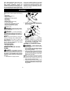
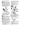
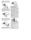
ADJUST AND SECURE THE HAN-
DLEBAR
DANGER:
Toavoidserious injury,the
barrier portion of the handlebar must be ad-
justed and remain installed as shown to pro-
vide a barrier between operator and the spin-
ning blade. The handlebar clamp must be
positioned between the arrowson thehandle-
bar decal.
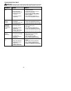
1. Lift handlebar to upright position.
Handlebar
2. Rotate handlebar/clamp counterclock-
wise toward engine until clamp falls into
groove of base.
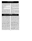
Handlebar
Handlebar
Clamp
Clamp
Knob
Clamp
Base
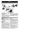
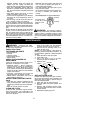
3. Place the handlebar in a comfortable
position.
4. Retighten handlebar by turning clamp
knob clockwise until handlebar is secure
and stationary in clamp base (clamp
knob can not be overtightened).
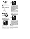
ASSEMBLY OF SHOULDER STRAP
WARNING:
Proper shoulder strap
and handlebar adjustments are required before
starting the engine.
1. Try on shoulder strap and adjust for fit and
balance befor estarting theengineorbegin-
ning a cutting operation.
2. Insert your right arm and head through
the shoulder strap and allow it to rest on
your left shoulder. Make sure the danger
sign ison yourback andthe hookis tothe
right side of your waist.
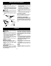
NOTE:
A one-half twist is built in the shoulder
strap to allow the strap to rest flat on the shoul-
der.
3. Adjust the strap, allowing the hook to be
about 6 inches below the waist.
4. Fasten the strap hook to the clamp located
between the triggerhandle and the handle-
bar clamp base and lift the tool to the oper-
ating position.