


8
OPERATION
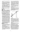
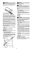
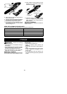
KNOW YOUR PRUNER ATTACHMENT
READ THIS INSTRUCTION MANUAL AND SAFETY RULES BEFORE OPERA T ING YOUR
PRUNER A TT ACHMENT. Compare the illustrations with your attachment to familiarize yourself with
the location of the various controls and adjustments. Save this manual for future reference.
Shaft
Pruner
Chain
Bar
Bar Nut
Hanger
Extension Shaft
Bar Oil Fill Cap
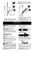
PRUNER
The PRUNER is designed for removal of
limbs and branches overhead not greater
than 6 inches (15 cm) in diam eter.
CHAIN TENSION
It is norm al for a new chain to stretch during
first 15 minutes of operation. You should
check your chain tension frequently. See
CHAIN TENSION intheSERVICE ANDAD-
JUSTMENTS section.
OPERATING THE COUPLER
Your unit is equipped with a coupler system
which enables optional attachments to be
installed. The optional attachments are:
MODEL:
Edger PPB1000E.....................
Cultivator PPB2000T..................
Blower PPB3000B....................
Pruner PPB5000P....................
Brushcutter* PPB4000C...............
*not designed for use with electric-powered
units.
WARNING: Always stopunitanddis-
connect spark plug wire (or disconnect unit
frompowersource)beforeremovingorinstal-
ling attachments.
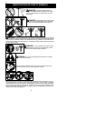
REMOVING PRUNER ATTACHMENT
(OR OTHER OPTIONAL ATTACH-
MENTS)
CAUTION:
When removingor installingat-
tachments, place the unit and attachment on
a flat surface for stability.
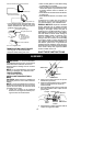
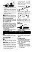
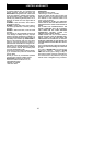
1. Loosen the coupler by turning the knob
counterclockwise.
Attachment
Coupler
Knob
LOOSEN
TIGHTEN
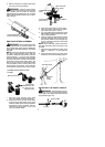
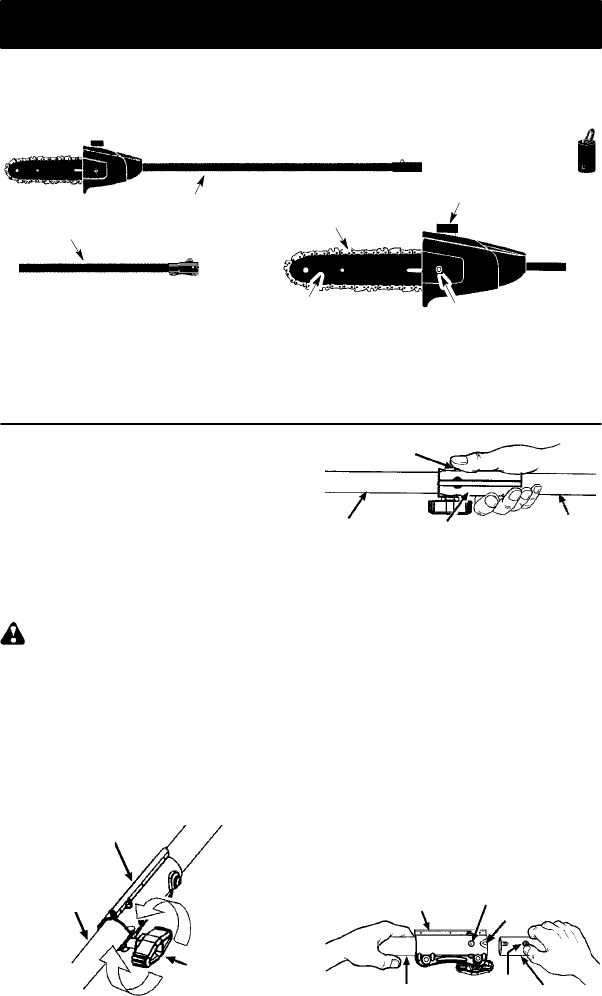
2. Pressandholdthelocking/releasebutton.
Locking/Release
Button
Coupler
Upper Shaft
Attachment
3. Whi le securely holding the eng ine end shaft
and extension shaft, pul l the attachment
straight out o f the extension shaft coupler.
4. Repeat steps to remove extension shaft
from coupler on engine end shaft.
INSTALLING OPTIONAL ATTACH -
MENTS
CAUTION:
DO NOT use extension shaft
with other optional attachments.
1. Removetheshaftcapfromtheattachment
(if present) and discard.
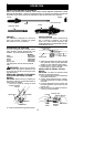
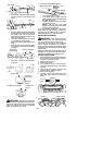
2. Position locking/release button of attach-
ment into guide recess of coupler onengine
end shaft.
3. Push the a ttachment into t he coupler until
the locking/release button snaps into the
primary hole.
4. Before using theunit, tightenthe knobse-
curely by turning clockwise.
Coupler
Primary Hole
Upper
Shaft
Locking/
Release
Button
Attachment
Guide Recess