


6
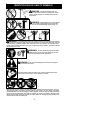
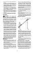
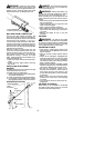
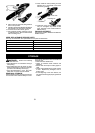
SmallRadiusTip
ReducedKickbackSymmetricalGuideBar
SymmetricalGuideBar
Large RadiusTip
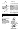
S Low--KickbackChain,designedwith acon-
toured depth gauge and guard link which
deflect kickback force and allow wood to
gradually ride into the cutter.
Low---Kickback
Chain
Not aLow---Kickback Chain
CanObstructMaterial
Contoured DepthGauge
Elongated GuardLink
Deflects
kickbackforce
and allowswood
tograduallyride
into cutter
TRANSPORTING AND STORAGE
S Do not grasp o r hold exposed blade.
S Stop unit before leaving work area.
S Allow unit and gearbox to cool before storing
or transporting it in a vehicle.
S Store unit and fuel in area where fuel vapors
cannot reach sparks oropen flamesfromwa-
ter heaters, electric motors or switches, fur-
naces, etc.
S Storeattachmentsoblade cannotaccidental-
ly cause injury .
S Storeattachmentindoors, outofreach ofchil-
dren.
If situations occur which are not covered in
this manual, use care and good judgm ent. If
you need assistance, call 1-800-554-6723.
SPECIALNOTICE: Exposure tovibrations
through prolonged use of gasoline powered
hand tools could cause blood vessel or nerve
damage in the fingers, h ands, and joints of
people prone to circulation disorders or abnor-
mal swellings. Prolonged use in cold weather
has been linked to blood vessel damage in
otherwise healthy people. If symptoms occur
such as numbness, pain, loss of strength,
change inskin color ortexture, orloss of feeling
in the fingers, hands, or joints, discontinue the
use of this tool a nd seek m edical a ttentio n. An
anti-vibration system does not guarantee the
avoidance of these problems. Users who oper-
atepower toolsona continualand regular basis
must monitor closely their physical condition
and the cond ition of this unit.
SAVE THESE INSTRUCTIONS
ASSEMBLY
WARNING: If received assembled,
repeatallstepstoensure yourunitisproperly
assembled and all fasteners are secure.
Examine parts fordamage. Do not use dam-
aged parts.
NOTE: If you need assistance or find parts
missing or damaged, call 1-800-554-6723.
TOOLS REQUIRED
S Hex wrench (provided)
INSTALL ING PRUNER ATTACH-
MENT
CAUTION:
When removingor installingat-
tachments, place theunit onaflat surfacefor
stability.
NOTE: The pruner attachment connects to
theengine endshaftthroughuseof acoupler
system. For extra reach, the extension shaft
(included) can be used.
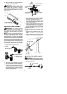
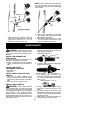
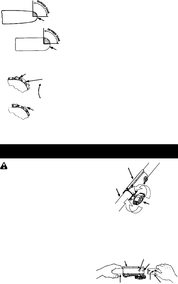
1. Loosen the couplers on the extension
shaft andontheengine endshaft byturn-
ing the knobs counterclockwise.
Attachment
Coupler
Knob
LOOSEN
TIGHTEN
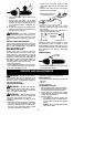
2. R emov e the shaft cap from the pruner
attachment (if present).
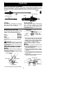
3. Position locking/release button of attach-
ment into guide recess of coupler on
extension shaft.
4. Push theattachment intothe coupleruntil
the locking/release button snaps into the
primary hole.
Coupler
Primary Hole
Upper
Shaft
Locking/
Release
Button
Attachment
Guide Recess
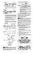
5. Repeat steps to attach extension shaft to
coupler on engine end shaft.