


7
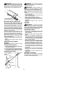
6. Before using the unit, tighten both knobs
securely by turning clockwise.
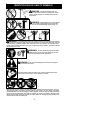
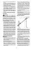
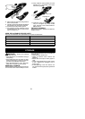
WARNING: Make sure the locking/
releasebutton i slocked intheprimary holeof
both couplers and the knobs are securely
tightened before op erating theunit. Usingthe
wrong holescould leadtoserious injury ordam-
age to the unit.
Locking/Release
Button in Primary Hole
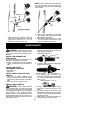
SHOULDER ST RAP ASSEMBLY
WARNING: Propershoulder strapand
handle adjustments are required before use.
The shoulder strap clamp must be installed as
shown above the assist handle on the engine
end shaft.
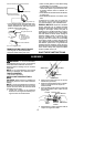
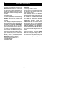
NOTE: Thelower shoulder strap clamphas
two spacer tabs attached. These tabs are
providedtoadaptthis attachmentforusewith
units that have a 1 inch (2,5 cm) diameter
shaft(theshoulderstrapclampwillnottighten
downsecurelyonthe1inch(2,5cm)diameter
shaft without using these spacer tabs). The
tabs must be broken of f completely before
use and placed over the screw holes on the
lower shoulder strap clamp. These tabs are
notneededforunitswitha7/8″(2,2cm)shaft.
Spacer Tabs
LOWER SHOULDER ST RAP
CLAMP
Spacer Tabs
positioned for use
on 1 inch (2,5 cm)
diameter shaft
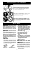
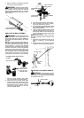
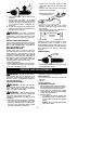
1. Place the upper shoulder strap clamp
over the shaft above the assist handle.
2. Position the lower shoulder strap clamp
underthe uppershaft andalign theupper
andlowerclampscrewholes (usespacer
tabs between upper and lower clamps if
necessary tosecureclamp, i.e.for 1inch
(2,5 cm) diameter shaft).
Upper Shoulder
Strap Clamp
Screws
Lower Shoulder
Strap Clamp
ENGINE/MOTOR
END
ATTACHMENT
END
3. Insert two screws into the screw holes.
4. Secure shoulder strap clamp by tighten-
ing screws with the hex wrench.
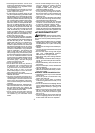
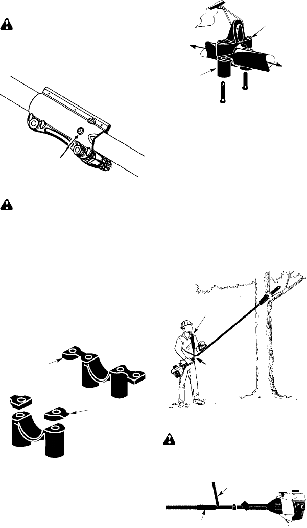
5. T ry on shoulder strap and adjust for fit and
balancebefore startingtheengineor b egin-
ning a cutting operation.
6. Insertyourrightarmandheadthroughthe
shoulder strapand allow ittorest onyour
left shoulder. Make sure the danger sign
isonyourbackandthehookisto theright
side of your waist.
NOTE: A one-half twist is built in the shoul-
der strap to allow the strap to rest flat on the
shoulder.
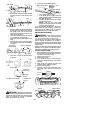
7. Adjust the strap, allowing the hook to be
about 3 -- 6 inches (8 -- 15 cm) below the
wai st.
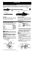
8. Fasten the strap hook totheupper clamp
and lift the tool to the operating position.
Shoulder Strap
Shoulder
Strap
Clamp
ADJUSTING THE ASSIST HANDLE
WARNING: When adjusting the as-
sist handle, besure it remains directly above
thecoupler ontheengineendshaft toensure
proper balancing of unit.
Assist Handle
Coupler