


12
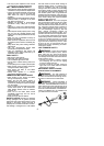
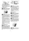
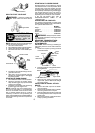
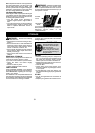
Air Filter
Button
Air Filter Cover
INSPECT MUFFLER AND SPARK
ARRESTING SCREEN
WARNING: The muffleron this prod-
uct contains chemicals known to the State of
California to cause cancer.
As your unit is used, carbondeposits buildup
onthe m uffler andspark arresting screen a nd
must be removed toavoid creating a firehaz-
ard or affecting engine performance.
For normal homeowner use, the muffler and
spark arresting screen will not require any
service. After 50 hours of use, we recom-
mend that your muf fler be serviced or re-
placed by an authorized service dealer.
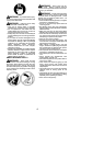
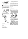
REPLACE SPARK PLUG
Replace the spark plug each year to ensure
the engine starts easier and runs better. In-
spec t spark plug every 25 hours of usage.
Cleanand/orreplaceasnecessary.Setspark
plug gap at 0.025 inch (0.6 mm). Ignition tim-
ing is fixed and nonadjustable.
1. Twist, then pull off spark plug boot.
2. Remove spark plug from cylinder and
discard.
3. Replace with Champion RCJ-6Y spark
plug and tighten securely with a 3/4 inch
(19 m m) socket wrench.
4. Reinstall the spark plug boot.
SERVICE AND ADJUSTMENTS
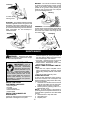
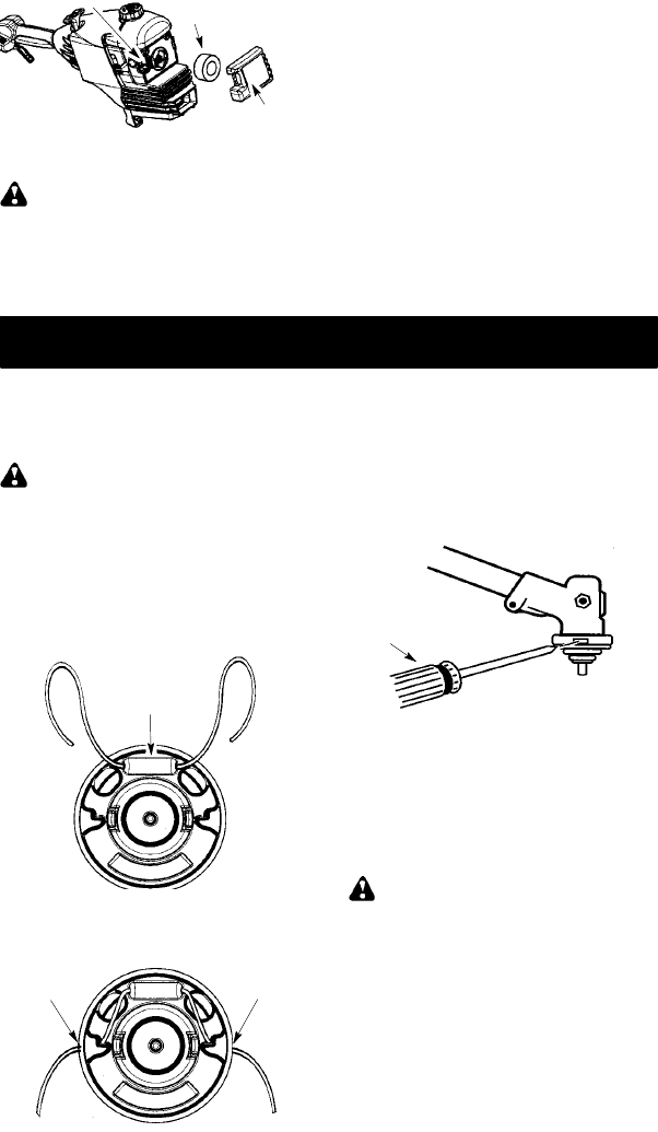
REPLACING THE LINE
For unit to operate properly, the cutting line
should be replaced when line becomes worn to
less than 3 inches in length from the edge of the
lineexit tunnels o n eachside ofthe cuttinghead.
WARNING: Only replace cutting line
with ON/OFF switch in the OFF position.
1. Remove and discard worn line before
installing new line.
2. Use only 0.115 inch (3 mm) diameter
Poulan PRO brand cut length line.
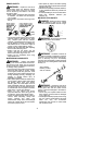
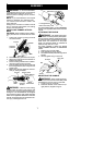
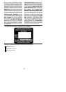
3. Insert one end of the line through the
positioning tunnel.
4. Continue to feed line through tunnel until
line is centered (leaving equal amounts
on each side). See illustration below.
Positioning
tunnel
5. Insert ends of lin e one at a time through
the line exit tunnels.
6. Pull theline and make sure the line is ex-
tended fully through the tunnels.
Line exit
tunnel
Line exit
tunnel
7. Correctly installed line will be the same
length on both ends.
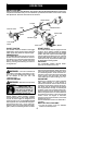
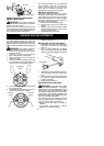
REPLACING T HE CUTTING HEAD
1. Align hole in the dust cup with the hole in
the side of the gearbox by rotating the
dust cup.
2. Insert a sm al l scre wd ri ver i n to a l i g ne d
holes. This will keep the shaft from turning
while removing andinstalling trimmer head.
Screwdriver
3. While holdingthe screwdriver in position,
remove trimmer head by turning clock-
wise.
4. Thread replacement trimmer head onto
the shaft by turning counterclockwise.
Tighten until secure.
5. Remove the screwdriver .
CARBURETOR ADJUSTMENT
WARNING: Keep others away when
making idle speed adjustments. The trimmer
head, blade or any optional attachment will be
spinning during most of this procedure. W ear
your protective equipment and observe all safe-
ty precautions. After making adjustments, the
trimmer head, blade or any optional attachment
must not move/spin at idle speed.
The carburetor has been carefully set at the
factory .Adjustments may benecessary ifyou
notice any of the following conditions:
S Engine will not idle when the throttle is
released.
S The trimmer head, blade or optional
attachment moves/spins at idle.