


9
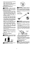
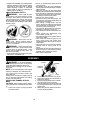
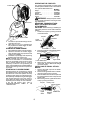
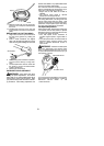
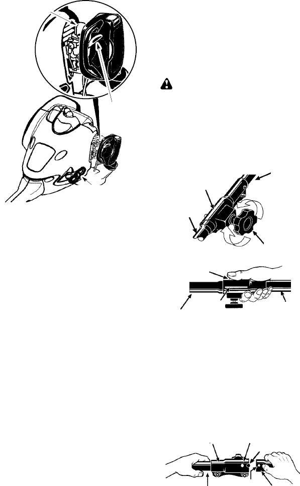
Primer Bulb
Start Lever
Starter Handle
5. Pull starter rope handle sharply until en-
gine starts and runs.
6. Allow unit to run for 10--15 seconds, then
fully squeeze the throttle trigger to disen-
gage the starting system.
STARTING A WARM ENGINE
1. Move ON/OFF switch tothe ON position.
2. Squeeze and hold the throttle trigger.
Keep throttle trigger fully squeezed until
engine runs smoothly.
3. Pull starter rope sharply while squeezing
throttle trigger until engine runs.
NOTE: Normally , the warm starting proce-
dure can be used within 5--10 minutes after
the unit is turned OFF. If the unit sits for more
than 10 minutes without being ran, it will be
necessary to start the unit by following the
steps under ST AR TING A COLD ENGINE or
following the starting instruction steps shown
on the unit.
START ING A FLOODED ENGINE
Flooded engines can be started by placing
the ON/OFF switch in the ON position. Move
the start lever to the RUN position and fully
squeeze throttle trigger. Pull the starter han-
dle repeatedly while squeezingthrottletrigger
until engine starts and runs. This could re-
quire pulling the starter handle many times,
depending on how badly the unit is flooded.
If the unit still doesn’t start, refer to
TROUBLESHOOTING TABLE or c all
1-800-554-6723.
OPERATING THE COUPL ER
This model is equipped with a coupler which
enables optional attachments to be installed.
The optional attachments are:
MODEL:
Edger PP1000E.....................
Cultivator PP2000T..................
Blower PP3000B....................
Brushcutter PP4000C................
Pruner PP5000P....................
WARNING: Always stopunit anddis-
connect spark plug beforeremoving orinstal-
ling attachments.
REMOVING TRIMMER ATTACH-
MENT (OR OTHER OPTIONAL
ATTACHMENTS)
CAUTION:
When removing or installing at-
tachments, place the unit on aflat surface for
stability .
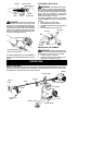
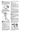
1. Loosen the coupler by turning the knob
counterclockwise.
Coupler
Knob
LOOSEN
TIGHTEN
Upper
Shaft
Lower
Attachment
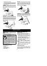
2. Press and hold the locking/release button.
L
ocking
/
Release
Button
Coupler
Upper Shaft
Lower Attachment
3. While securely holding the engine and
upper shaft, pull the a ttachment straight
out of the coupler.
INSTALLING OPTIONAL ATTACH -
MENTS
1. Remove the shaft cap from the attach-
ment (if p resent).
2. Position locking/release button of a ttach-
ment into guide recess of coupler .
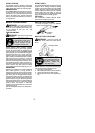
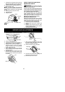
3. Push theattachment intothe coupleruntil
the locking/release button snaps into the
primary hole.
4. Before usingthe unit, tightenthe k nobse-
curely by turning clockwise.
Coupler Primary Hole
Upper
Shaft
Locking/
Release
Button
Attachment
Guide Recess