7
Theextensioncordusedtoreachthe
power source must be:
D Specifically marked as suit able f or out-
door u se. The cord m ust b e marked with
thesuffix“W-A”(inCanada“W”).
D Heavy enough to carry full current f rom
the power source to the unit. Otherwise,
loss of power a nd o ve rheating can occur
causing damage to unit. Refer to table for
minimum wire gauge recommendations.
The cord must be marked with t he proper
wire gauge. (Appropriate extension cords
are a vailable.) Do not u se m ultiple cords.
D In good condition. Cord insulation must
be intact with no cracks or deterioration.
Plug connectors must be un damaged.
DO NOT use mult iple cords.
MINIMUM W IRE GAUGE
RECOMMENDATIONS
VOLTS
25 FT. 50 FT. 100 FT.
120 16
A.W.G.*
16
A.W.G.*
*American Wire Gauge
14
A.W.G.*
Secur e the extensi on cord to the unit b y
threading the cord through the cord re-
tainer (see illustration). Insert the cord
rece ptacl e in t o th e recesse d p l ug .
CAUTION: Failuretousecordretain-
er could result in damage to the unit,
extension cord, or both.
Cord
Retainer
Cord
Receptacle
Recessed
Plug
on Unit
USING YOUR UNIT
KNOW YOUR ELECTRIC BLOWER
READ THIS INSTRUCTION MANUAL AND SAFETY RULES BEFORE OPERATING YOUR
UNIT.
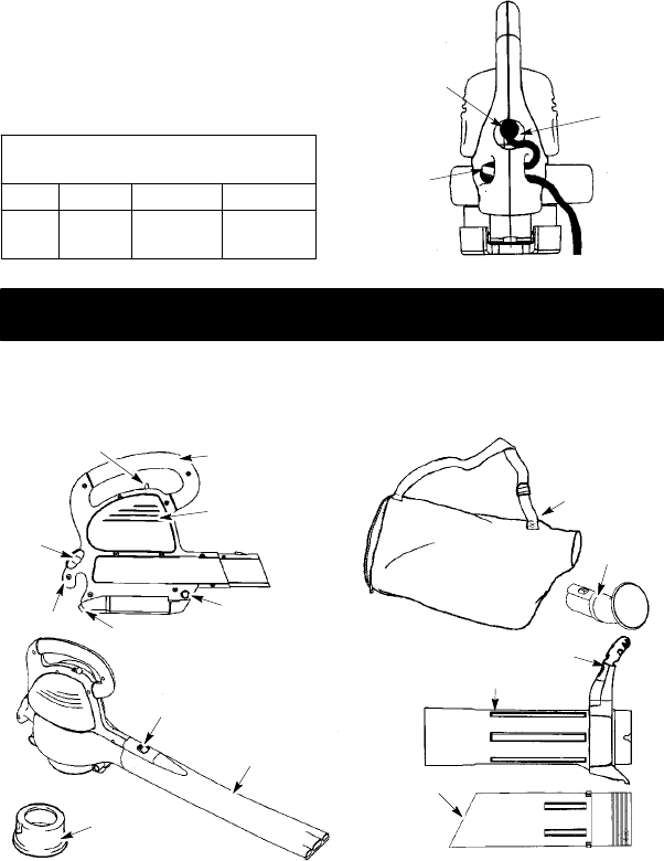
Compare the illustrations to y our unit to familiarize yourself with the location of
the various controls and adjustments. Save this manual for future reference.
Top Handle
Air Vents
ON
/
OFF Switch
Inlet Cover
Latch
Rear
Handle
Upper Vacuum Tube
Lower Vacuum Tube
Collection Bag
Blower Tube
Cord
Retainer
Inlet Restrictor
Vacuum Assist Handle
Tube Release Button
Elbow
Tube
Upper Vacuum Tube
Retaining P ost
ON/OFF SWITCH
The
ON/OFF SWITCH is used to activate
the motor.
INLET COVER LATCH
TheINLETCOVERLATCH isused toopen
and close the inlet cover and to secure
the upper vacu um tube to the blower
unit.


