


-- 3 --
plug disconnected. Keep vents and dis-
charge tubes free of debris which can ac-
cumulate and restrict proper air flow.
D
Never place any object in the air intake
opening as this could restrict pr oper air flow
and cause damage to the uni t.
D
Never use for spreading chemicals, fertil-
izers, orother substances which maycon-
tain toxic materials.
D
To avoid spreading fire, do not use near
leaf or brush fires, fireplaces, barbecue
pits, ashtrays, etc.
D
Use only for jobs explained in this manual.
MAINTAIN YOUR UNIT PROPERLY
D
Have all maintenance other than the r ec-
ommended procedures described in the in-
struction manual performed by an autho-
rized service dealer.
D
Disconnect spark plug bef or e perform ing
maintenance except for carbur etor adjust-
ments.
D
Use only recommended Poulan PRO
!
re-
placement parts; use of any other parts
may void your warranty and cause damage
to your unit.
D
Empty fuel tank before storing the unit. U se
upfuelleft incarbur etorby starting engineand
letting it run until it stops.
D
Do not use any accessory or attachment
other than those recommended by manufac-
turer for use with your unit.
D
Do not store the unit or fuel in a closed area
where fuel vapors can reac h sparks or an
open flame from hot water heaters, electric
motors or switches, furnaces, etc.
D
Store in a dry area out of reach of children.
SPECIAL NOTICE:
Exposure to vibra-
tions through prolonged use of gasoline pow-
ered hand tools could cause blood vessel or
nerve damage in the fingers, hands, and
joints of people prone to circulation d isorders
or abnormal swelling. Prolonged use in cold
weather has been linked toblood vessel dam-
age in otherwise healthy people. If symptoms
occur such as numbness, pain, loss of
strength, change in skin color or texture, or
loss of feeling in the fingers, hands, or joints,
discontinue the use of this t ool and seek
medical attention. An antivibration system
does not guarantee the avoidance of these
problems. Users who operate power tools on
a continual and regular basis must monitor
closely their physical condition and the condi-
tion of this tool.
SPECIAL NOTICE:
For users on U .S. For-
est Land and in some states, including Cali-
fornia (Public Resources Codes 4442 and
4443), Idaho, Maine, Minnesota, NewJersey,
Oregon, and Washington: Certain internal
combustion engines operated on forest,
brush, and/or grass covered land in theabove
areas are required to be equipped with a
spark arresting screen, maintained in effec-
tive working order, orthe engine must be con-
structed, equipped, and m aintained for the
prevention of fire. Check with your state orlo-
cal authorities for regulations pertaining to
these requirements. Failure to follow these
requirements isa violation of the law. This unit
is not factory equipped with a spark arresting
screen; however, a spark arresting screen is
available as an optional part. If a spark arrest-
ing screen is required in your area, contact
your authorized service dealer for the correct
kit. The spark arresting screen, blower tubes,
and nozzles must be assembled to unit to be
in full compliance with r egulations.
ASSEMBLY
WARNING:
Stop engine and be sure
the impeller blades have stopped turning be-
fore opening the vacuum inlet door or at-
tempting to insert or remove the vacuum or
blower tubes. The rotating blades can cause
serious injury. Always disconnect the spark
plug before performing maintenance or ac-
cessing movable parts.
WARNING:
If you receive your unit
assembled, check each step to insure your
unit is properly assembled and all fasteners
are secure. Follow all safety information in
the manual and on the unit.
D
A standard screwdriver is required for as-
sembly.
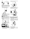
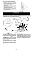
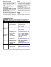
BLOWER TUBE ASSEMBLY
1. Align the rib on the blower tube with the
groove in the blower out let; slide the tube
into place.
NOTE:
Knob must be loose enough to allow
blower tube to be inserted in blower outlet.
Loosen knob by turning counterclockwise.
Blower
Tube
Blower
Outlet
Rib
Groove
2. Secure the tube by turning the knob clock-
wise.
3. Toremove the tube, turn the knob counter-
clockwise to loosen the tube; remove the
tube.
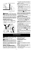
VACUUM BAG ASSEMBLY
1. Open the zipper on the vacuum bag and
insert the elbow tube.
2. Push the small end of the elbow tube
through the s mall opening in the bag.