


6
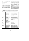
ASSEMBLY INFORMATION -- WEED
BLADE
WEED
BLADE
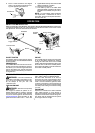
NOTE: Remove the trimmer head and plastic
shield before attaching the metal shield and
installing the weed blade. To remove the trim-
mer head,align h ole i n t he du st cup with thehole
in the side of the gearbox by rotating the dust
cup. I nsert a small screwdriver into aligned
holes. This will keep the shaft f rom turning w hile
loosening the t rimmer head . Remove the trim-
mer head by turning clockwise. Remove the
screwdrive r. To remo ve the plastic shi el d, loo s-
en and rem ove wing nut. Pivot shield to release
bracket from slot. See INSTALLATION OF
THECUTTINGHEADandATTACHINGTHE
PLASTIC S HIELD forillustrations. Besureto
store all parts and instructions for future use.
Never use the trimmer head with the metal
blade installed.
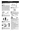
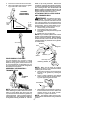
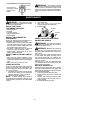
ATTACHING THE METAL SHIELD
WARNING: The m etal shield must
be properly installed on the tool anytime the
tool isused witha blade.The forwardtip o fthe
metal shield helps to reduce t he occurrence
of bladethrust which cancause seriousinjury
such as amputation to the operator or by-
standers. Failure to install the shield in the
position shown can result in serious injury to
the operator. The lengthof the shield must be
aligned with the length of the tube.
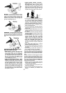
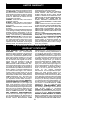
1. Place t he m etal shield unde r t he gea rbox,
and align the screw ho le s.
Shield
Gearbox
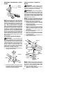
2. Insert and thread the 4 mounting screws
through the holes of the gearbox and the
metal shield. Tightenevenly and secure-
ly with the hex wrench provided.
INSTALLATION OF THE METAL
BLADE
WARNING: Wear protective gloves
when handling or performing maintenance on
the blade to avoid i njury. The blade is sharp a nd
can cut you e ven w hen it is not moving.
WARNING: Do not use any blades, or
fastening hardware other than the washers and
nuts shown in the following illustrations. These
parts must be provided by Poulan/Weed Eater
and installed as shown below. Failure to use
proper parts can cause t he blade t o fly of f and
seriously hur t you or others.
NOTE: The dust cup and retaining washer are
located on t he gearbox shaft andnot in t he pa rts
bag. All other fasteners mentioned in t he follow-
ing assembly steps are in t he parts bag.
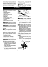
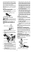
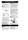
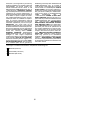
1. Remove the retaining washer from the
threaded shaft ofthe gearbox. Leavethe
dust cup on the shaft.
2. Install the bladeand the r etainingwasher
over the threaded shaft.
3. Make sure the raised part of theretaining
washer is facing the gearbox and the
raised area fits into the hole in the center
of the blade.
4. Slide the blade and retaining washer onto
the shaft o f the gearbox.
5. Place the cupped washer onto the shaft.
Make sure thecupped side ofthe washer
is toward the blade.
6. Install the bladenut by threading ontothe
shaft counterclockwise.
Shield
Blade
Retaining
Washer
Dust Cup
Cupped
Washer
Nut
Threaded Shaft
Gearbox
NOTE: Make sure all parts are in place as i l-
lustrated, and the blade is sandwiched between
the dust cup and the retaining washer. There
should be no space between the blade and the
dust cup or t he retaining washer.
7. Align hole in dust cup with hole in side of
gearbox by rotating the blade.