


17
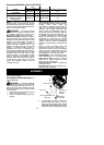
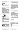
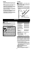
Depth Gauge
File
File Holder
Cutter
90˚
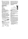
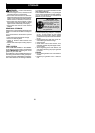
S Align the 30˚ f ileholder marks paral-
lelwiththebar andto thecenter ofthe
chain.
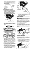
Cutter
Cutter
30˚
File Holder Line
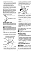
S Sharpen cutters on one side of the
chain first. File from the inside of e ach
cutter to the outside. Then, turn the
chain saw around and repeat the pro-
cess for th e ot her side o f the ch ain.
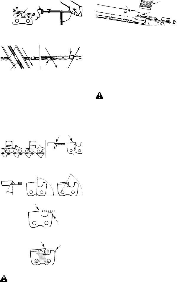
S Fileon theforward strokeonly. Use 2
or 3 strokes per cutting edge.
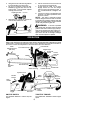
S Keep all cutters the same length
when filing.
S File enough to remove any damage
to cutting edges (side plate and top
plate of cutter).
A
ll Cutters
Same Length
Remo
v
e D amage
Top P late
Side Plate
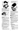
S File chain to meet the s pecifications
as shown.
30˚
80˚
60˚
Rounded
Corner
0.025 inch
(0.65 mm)
Right
Hook Angle
Wrong
Squared O
f
f
Corner
Too Much Hook
A
ngle
WARNING: Maintain the p roper
hook angle according to the manufacturer’s
specifications for the chain you are using. Im-
proper hook angle will increase the chance of
kickback which can result in serious injury.
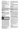
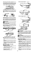
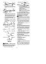
4. Check and low er depth gauges.
Depth Gauge Tool
Depth Gauge
File
S Place gauge tool on cutter.
S If the depth gauge is higher than the
depth gaugetool, file itlevelto the topof
the depth gauge tool.
S Maintain rounded front corner of
depth gauge with a flat file.
NOTE: The very top of the depth
gauge should be flat with the front
half rounded off w ith a flat file.
If you require further assistance or are unsure
about performing this procedure, contact your
authorized service dealer or call our customer
assistance help line at 1--800--554--6723.
CARBURETOR ADJUSTMENT
WARNING: The chain w ill be mov-
ing during most of this procedure. Wearyour
protective equipment and observe all safety
precautions. Thechain must notmoveatidle
speed.
The carburetor has been carefully se t at the
factory. Adjustments may be necessary if
you notice any of the f ollowing conditions:
S Chain moves at idle. See IDLE SPEED--T
adjusting procedure.
S Saw w illnot idle. See IDLESPEED--T ad-
justing procedure.
Idle Speed--T
Allow engine to idle. If the chain m oves, idle i s
too fast. Iftheengine stalls, idleis tooslow . Ad-
just speed until engine runs without chain
movement (idle too fast) or stalling (idle too
slow). The idle speed screw is located in the
area above the primer bulb and is labeled T.
S Turn idle screw (T) clockwise to inc rease
engine speed.
S Turn idle screw (T) counterclockwise to
decrease engine speed.
If you require further assistance or are unsure
about performing this procedure, contact your
authorized service dealer or call our customer
assistance help line at 1--800--554--6723.
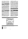
COOLING SYSTEM
To keep the working temperature as low as
possible the machine is equipped with a
cooling system.
The cooling system consists of:
S Air intake on the starter
S Air guide plate
S Fins on the flywheel
S Cooling fins o n the cylinder
S Cylinder cover (directs cold air over the
cylinder)
Clean the cooling s ystem with a brush after
each use, more often in demanding condi-
tions. A dirty or blocked cooling system re-
sults i n the machine overheating which
causes dam age to the piston and cylinder.