


5
Locking/Release
Button in Primary Hole
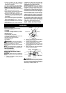
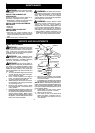
HANDLEBAR ASSEMBLY
DANGER:RISKOFCUT. To avoidse-
rious injury, the barrier portion of the handle-
bar must be installed as shown on the upper
shaft of thepowerheadto provide abarrier be-
tweenoperator andthespinningblade. Attach
handlebar mounting bracket above arrow o n
safety warning decal on the upper shaft(pow-
erheadend ofunit). Ensurehandlebar is posi-
tioned on mounting bracket a t the end of the
arrow on the handlebar decal.
NOTE: Two mounting brackets are included
with this attachment. Both brackets are provided
to adapt this attachment for use with power-
heads that have either a1″ (2.5 cm) diameteror
a7/8″ (2.2 cm) d iameter upper shaft. The cor-
rect bracket must be used to ensure that the
handlebar is mounted securely to the upper
shaft before use.
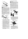
Screw
Mounting
Bracket
Handlebar
Bracket Cover
1. Place the mounting bracket over t he up-
per shaft above the arrow on the safety
label. Be sure to use the correct m ount-
ing bracket for either the 1 ″ (2.5 cm) or
7/8″ (2.2 cm) diameter upper shaft.
2. Position one of the bracket covers under
the upper shaft and align t he mounting
bracket and th e b ra cke tcover screw ho l es.
Insert two screws into the screw holes.
3. Secure the mounting bracket by tighten-
ing the screws with the hex wrench.
4. Locate the decal on the handlebar . This
decal includes an arrow . Position th e
handlebar with the mounting bracket at
the end of the arrow.
5. Position the second bracket cover over
the handlebar. Align the mountingbrack-
et and the bracket cover screw holes.
Again make sure the handlebar is at the
end of the arrow.
6. Insert two screws and hand tighten only .
Be sure the handlebar is installed cor-
rectly; then, tighten each screw securely
with the hex wrench.
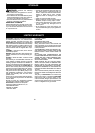
SHOULDER STRAP ASSEMBLY
WARNING: Proper shoulder strap
and handlebar adjustments must be made
with theengine completely stoppedbeforeus-
ing unit. The sho ulder strap cla mp must be
installed as shown above the handlebar on the
upper shaft (powerhead end of unit).
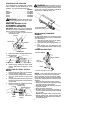
NOTE: The lower shoulder strap clamp has
twospacertabs attached. Thesetabs arepro-
vided to adapt this attachment for use with
powerheads that have a 1″ diameter upper
shaft (the shoulder strap clamp will nottighten
down securely on the 1″ diameter upper shaft
without using these spacer tabs). The tabs
must be broken off completely before useand
placed over the screw holes on the lower
shoulder strap clamp. These tabs are not
needed for powerheads with a 7/8″ upper
shaft.
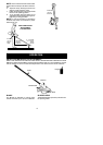
Spacer Tabs
LOWER SHOULDER STRAP
CLAMP
Spacer Tabs
positioned for use
on 1″ diameter
upper shaft
1. Place the upper shoulder strap clamp
overtheuppershaftabovethehandlebar.
2. Position the lower shoulder strap clamp
under the upper shaft and align theupper
and lower clamp screw holes (use
spacer tabs between upper and lower
clamps if necessary tosecure clamp, i.e.
for 1″ diameter upper shaft).
Upper Shoulder
Strap Clamp
Screws
Lower Shoulder
Strap C lamp
POWERHEAD
END
ATTACHMENT
END
3. Insert two screws into the screw holes.
4. Secure shoulder strap clamp b y tighten-
ing screws with the hex wrench.
5. Insert your right arm and head through
the shoulder strap and allow it to rest on
your left shoulder. Make sure the danger
sign is onyourback andthe hook is tothe
right side of your waist.