


7
30 inches
(76 cm)
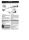
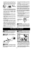
CONFIGURING YOUR UNIT
You can configure your unit using acutting head
for grass and light weeds, or a weed blade for
cutting grass, weeds, and brush up to 1/2 inch
(1 cm) in diameter . To assemble your unit, go to
the section for the desired configuration andfol-
low the instructions.
ASSEMBLY INFORMATION --
TRIMMER HEAD
TRIMMER
HEAD
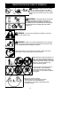
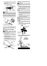
NOTE:Remove theblade andmetal shield be-
fore attaching the plastic shield and trimmer
head. To r emove b lade, align hole in the dust
cup with the holein theside ofthe gearboxby
rotating the blade. Insert a small screwdriver
intoaligned holes. This willkeeptheshaft from
turning while loosening the blade nut. Remove
blade nut by turning clockwise. Remove the
screwdriver . Remove both washers and blade.
To remove metal shield, loosen and remove the
four mounting screws. See ATT ACHING THE
MET AL SHIELD and INST ALLATION OF THE
MET ALBLADE forillustrations. Besure tostore
all parts and instructions for future use.
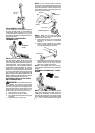
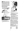
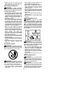
ATTACHING T HE PLASTIC SHIELD
ANDTRIMMERHEAD
WARNING: The shieldmustbeprop-
erly installed. The shield provides partial
protection tothe operator andothers fromthe
risk of thrown objects, and is equipped with a
line limiterblade whichcuts excess lineto the
proper length. The line limiter blade (on un-
derside of shield) is sharp and can cut you.
1. Remove wing nut from shield.
2. Insert bracket into slot on shield.
3. Pivot shielduntil boltpasses t hroughhole
in bracket.
4. Tighten the wing nut securely.
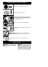
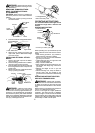
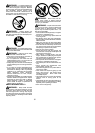
NOTE: If your unit has a plastic cover over
thethreads onthe threadedshaft, removethe
covering toexpose thethreads. Beforeinstal-
lingthe trimmerhead,makesurethe dustcup
and retaining washer are positioned on the
gearbox as shown below.
Wing Nut
Retaining Washer
Dust Cup
Bracket
Slot
Shield
Gearbox
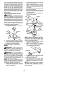
NOTE: Make sure all parts are properly
installed as shown in the illustration b efore
installing the trimmer head.
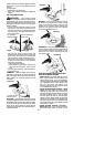
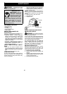
5. Align hole in the dust cup with the hole in
the side of the gearbox by rotating the
dust cup.
6. Insert a small screwdriver into aligned
holes. This will keep the shaft from turn-
ing while tightening trimmer head.
Screwdriver
7. While holdingthescrewdriver inposition,
thread trimmer head onto the shaft in the
direction shown on the decal (counter-
clockwise). Tighten until secure.
NOTE: The retaining washer must be posi-
tioned with the raised section facing toward the
gearbox.
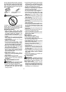
ASSEMBLY I NFORMATION -- WEED
BLADE
WEED
BLADE
NOTE: Remove the trimmer head and plastic
shield before attaching the metal shield and
installing the weed blade. To remove the trim-
mer head,alignhole inthedust cup withthehole
in the side of the gearbox by rotating the dust
cup. Insert a sm all sc rewdri v er into ali gned