


6
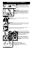
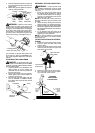
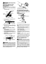
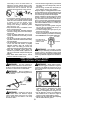
5. Push theattachmentintothe coupleruntil
the locking/release button snaps into the
primary hole.
6. Before using the unit, tighten the knob se-
curely by turning clockwise.
Coupler
Primary Hole
Upper
Shaft
Locking/
Release
Button
Lower
Attachment
Guide Recess
WARNING: Make sure the locking/
release button is locked in the primary hole
and theknob is securely tightened beforeop-
erating the unit.All attachments aredesigned
to be used in the p rimary hole unless other-
wise stated in the applicable attachment in -
struction manual. Using thewrong hole could
lead to serious injury or dama ge to the unit.
Locking/Release
Button in Primary Hole
For assembly of optional attachments (see
list on page10), refer tothe ASSEMBLY sec-
tion of the applicable attachment instruction
manual.
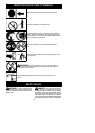
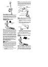
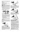
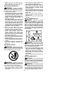
ATTACH ING THE HANDLEBAR
DANGER: To avoid serious injury , the
barrier portion ofthe handlebar must beinstalled
as shown to provide a barrier between operator
and the spinning blade.
1. Locate t he decal on the handlebar. This
decal includes an arrow. Position the
handlebar with the mounting bracket at
the end of the arrow.
2. Position the bracket cover over the han-
dlebar. Again make sure thehandlebar is
at the end of the arrow.
3. Insert screws and hand tighten only . Be
sure the handlebar is installed correctly;
then, tighten each screw securely with the
hex wrench.
Screw
Mounting
Bracket
Handlebar
Bracket Cover
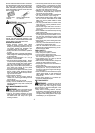
ASSEMBLY OF SHOULDER STRAP
WARNING: Proper shoulder strap
and handlebar adjustments must be made
with the engine completely stopped before
using unit.
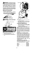
1. Insert your right arm and head through
the shoulder strap and allow it to rest on
your left shoulder. Make sure the danger
sign isonyourback andthehook istothe
right side of your waist.
NOTE: A one-half twist i s built in the shoul-
der strap to allow the strap to rest flat on the
shoulder.
2. Adjust the strap, allowing the hook to be
about 6 inches (15 cm) below the waist.
3. Fasten the strap hook to the clam p located
between the trigger handle and the handle-
bar clamp base and lift the tool to the oper-
ating position.
4. Try on shoulder strap and adjust for fit
and b alance before startingthe engineor
beginning a cutting operation .
NOTE: It m ay be necessary to relocate the
shoulder strap clamp on the shaft for proper
balancing of unit.
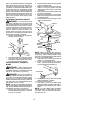
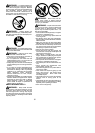
TO RELOCATE SHOULDER STRAP
CLAMP:
1. Loosen and remove both clamp screws.
2. Place the upper shoulder strap clamp
over the shaft.
3. Position th e lower shoulder strap clamp
under the shaft and align the upper and
lower clamp screw holes.
Upper Shoulder
Strap Clamp
Screws
Lower Shoulder
Strap Clamp
4. Insert two screws into the screw holes.
5. Secure shoulder strap clamp by tighten-
ing screws with a hex wrench.
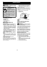
30 inches
(76 cm)
HARNESS
ADJUSTMENT
FOR BALANCE
4 -- 12 inches
(10 -- 30 cm)
above
ground
6 inches
(15 cm)
below
waist