


9
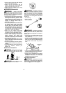
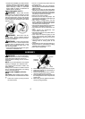
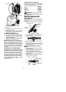
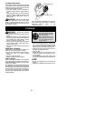
Primer Bulb
Start Lever
Starter Handle
5. Pull starter rope handle sharply until en-
gine starts and runs.
6. Allow u nit to run for 10--15 seconds, then
fully squeeze the throttle trigger t o disen-
gage the starting system.
STARTING A WARM ENGINE
1. Move ON/OFFswitch to theON position.
2. Squeeze and hold the throttle trigger.
Keep t hrottle t rigger fully squeezed until
engine runs smoothly.
3. Pull starter rope sharply while squeezing
throttle trigger until engine runs.
NOTE: Normally, the warm starting proce-
dure can be used within 5--10 minutes after
the unit is turned OFF. If the unit sits for more
than 10 minutes without being ran, it will be
necessary t o start the unit by following the
steps under STARTING A COLD ENGINE or
following the starting instruction steps shown
on the unit.
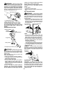
STARTING A FLOODED ENGINE
Flooded engines can be started by placing
the ON/OFF switch in the ON position. Move
the start lever to the RUN position and fully
squeeze throttle trigger . Pull the starter han-
dlerepeatedly whilesqueezing throttletrigger
until engine starts and runs. This could re-
quire pulling the starter handle many times,
depending on how badly the unit is flooded.
If the unit still doesn’t start, refer to
TROUBLESHOOTING TABLE or call
1-800-554-6723.
OPERATING THE C OUPL ER
This model is equipped with a coupler which
enables optional attachments to be installed.
The optional attachments are:
MODEL:
Edger PP1000E.....................
Cultivator PP2000T..................
Blower PP3000B....................
Brushcutter PP4000C................
Pruner PP5000P....................
WARNING: Always stopunit anddis-
connect spark plug before removing orinstal-
ling attachments.
REMOVING TRIMMER ATTACH-
MENT (OR OTHER OPTIONAL
ATTACHMENTS)
CAUTION:
When removing or installing at-
tachments, place the unit on a flat surface for
stability.
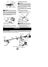
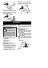
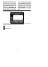
1. Loosen the coupler by turning the knob
counterclockwise.
Coupler
Knob
LOOSEN
TIGHTEN
Upper
Shaft
Lower
Attachment
2. Press and h old the locking/release b utton.
L
ocking
/
Release
Button
Coupler
Upper Shaft
Lower Attachment
3. While securely holding the engine and
upper shaft, pull the attachment s traight
out of the coupler .
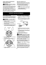
INSTALLING OPTIONAL ATTA CH -
MENTS
1. Remove the shaft cap fr om the attach-
ment (if present).
2. Position locking/release button of a ttach-
ment into guide recess of coupler.
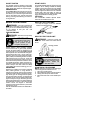
3. Pushthe attachment intothecoupler until
the locking/release button snaps into the
primary hole.
4. Before using theu nit,tightenthe knobse-
curely by t urning clockwise.
Coupler Primary H ole
Upper
Shaft
Locking/
Release
Button
Attachment
Guide Recess