


-- 5 --
ASSEMBLY
WARNING: Stop engine andbe sure
the impeller blades have stopped turning be-
fore opening the vacuum inlet door or at-
tempting to insert or remove the vacuum or
blower tubes. The rotating blades can cause
serious injury . Always disconnect the spark
plug before performing m aintenance or ac-
cessing movable parts.
WARNING: If you receive your unit
assembled, check each step to insure your
unit is properly assembled and all fasteners
are secure. Follow all safety inform ation in
the manual and on the unit.
D A standard screwdriver is required for as-
sembl y.
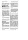
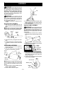
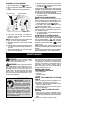
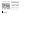
BLOWER TUBE ASSEMBLY
1. Align the rib o n t he bl ower tube with t he
grooveinthebloweroutlet;slidethe tubeinto
place.
NOTE: Knobmustbe looseenough toallow
blower tube to be inserted in blower outlet.
Loosen knob by turning counterclockwise.
Blower
Tube
Blower
Outlet
Rib
Groove
2. Secure the tube by turning the knob clock-
wise.
3. To remove the tube, turn the knob counter-
clockwise t o loosen the t ube; remove t he
tube.
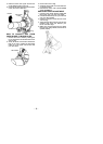
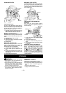
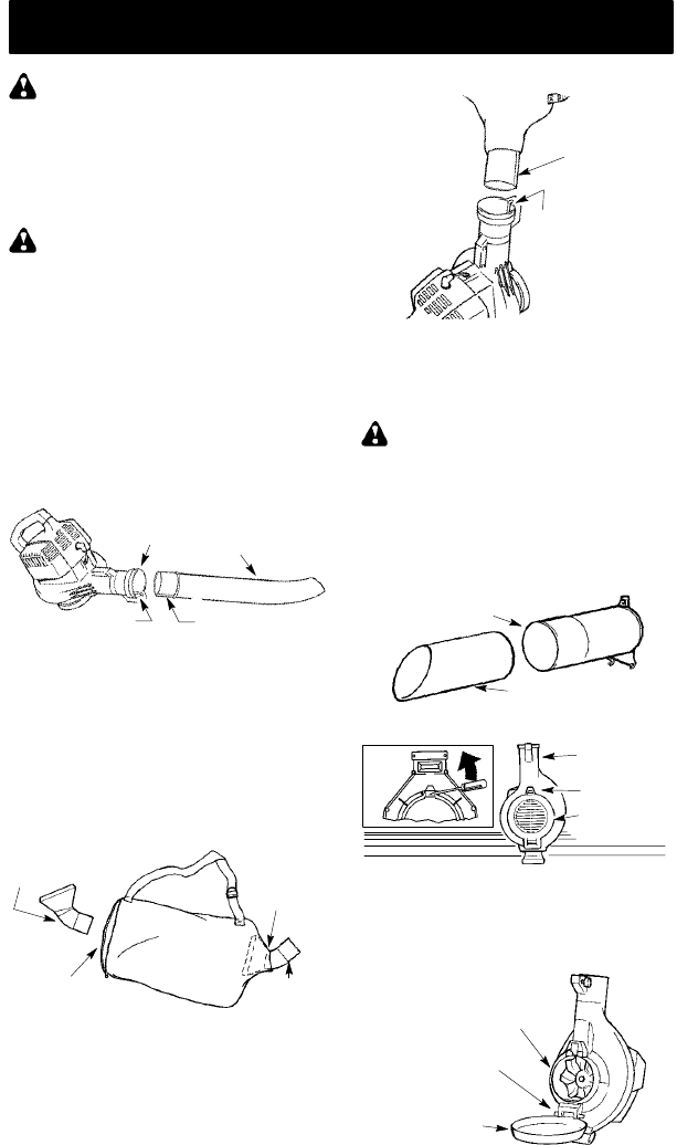
VACUUM BAG ASSEMBLY
1. Open the zipper on the vacuum bag and in-
sert the elbow tube.
2. Push the small end of the elbow tube
through the small opening in the bag.
Small
Opening
Zipper
Opening
Elbow
Tube
Rib
NOTE: M akesureedgeofthesmallopening
is flush against the flared area of the elbow
tube, and the rib on the elbow tube is on the
bottom.
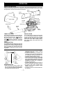
3. Close the zipper on the bag. Make sure the
zipper is closed comp letely.
4. Remove blower tube from engine.
Rib
Groove
5. Insert the elbow tube into the blower outlet.
Make sure elbow tube rib is aligned with the
blower outlet groove.
6. Turn knob clockwise to secure elbow tube.
VACUUM TUBE ASSEMBLY
WARNING: Stop engineand be sure
the impeller blades have stopped turning be-
fore opening the vacuum inlet door or at-
tempting to insert or remove the vacuum or
blower tubes. The rotating blades can cause
serious injury.
1. Align the lower vacuum tube as shown.
Push lower vacuum tube intoupper vacuum
tube.
Lower Vacuum Tube
Upper Vacuum
Tube
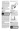
2. Insert the tip of a screwdriver into the latch
area of the vacuum inlet.
Latch Area
Blower
Outlet
Vacuum
Inlet Cover
Latch
Area
3. Gently tilt the handle of the screwdriver to-
ward the back of the unit torelease thelatch
while pulling up on the vacuum inlet cover
with your ot her hand.
4. Hold thevacuuminlet cover openuntilupper
vacuum tu be is installed.
Vacuum Inlet
Vacuum
Inlet
Cover
Retaining Post