


11
NOTE:
If engine dies with the choke lever
in th e OFF CH OKE positio n, mo ve th e
choke lever to th e HAL F CHOKE position
and pull the rope until engine runs, but no
more th a n 6 pulls.
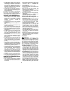
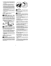
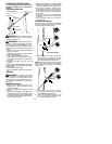
Choke
position
decal
STARTING A WARM ENGINE
1. Move ON/OFFswitch tothe ONposition.
2. Move the choke lever to the HALF
CHOKE position.
3. Squeeze and hold the throttle trigger.
Keep throttle trigger fully squeezed until
the engine runs smoothly .
4. Pullstarterropesharplyuntil engineruns,
but no more than 5 pulls.
5. Allow engine to run 15 seconds, then
movethechokelevertotheOFFCHOKE
position.
NOTE:
If engine has not started, pull starter
rope5morepulls.If enginestill doesnotrun,it
is probably flooded.
STARTING A FLOODED ENGINE
Flooded engines can be started by placing
the choke lever in the OFF CHOKE position;
then, pull the rope to clear the engine of ex-
cess fuel .Thiscouldrequirepullingthestarter
handle many times depending on how badly
the unit is flooded.
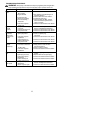
If the unit still doesn’t start, refer to
TROUBLESHOOTING TABLE or call
1-800-554-6723.
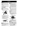
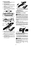
OPERATING THE COUPLER
This model is equipped with a coupler which
enables optional attachments to be installed.
The optional attachments are:
MODEL:
Edger PP1000E.......................
Cultivator PP2000T....................
Blower PP3000B......................
Brushcutter PP4000C..................
W ARNING:
Always stopunitanddis-
connect sparkplug beforeremovingor instal-
ling attachments.
REMOVING PRUNER ATTACHMENT
(OR OTHER OPTIONAL ATTACH-
MENTS)
CAUTION:
Whenremovingor installing at-
tachments, place the unit on aflat surfacefor
stability.
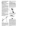
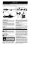
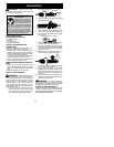
1. Loosen the coupler by turning the knob
counterclockwise.
Coupler
Knob
LOOSEN
TIGHTEN
Upper Shaft
Lower
Attachment
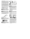
2. Press and hold the locking/release button.
Locking/Release
Button
Coupler
Upper Shaft
Lower Attachment
3. While securely holding the engine and
upper shaft, pull the attachment straight
out of the coupler.
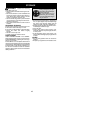
INSTALLING OPTIONAL ATTACH -
MENTS
1. Remove the shaft cap from the attach-
ment (if present).
2. Position locking/release buttonof attach-
ment into guide recess of coupler.
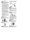
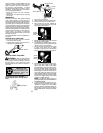
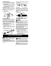
3. Push theattachmentintothecoupleruntil
the locking/release button snaps into the
primary hole.
4. Beforeusingtheunit, ti ghtenthe k nobse-
curely by turning clockwise.
Coupler
Primary Hole
Upper
Shaft
Locking/
Release
Button
Attachment
Guide Recess
W ARNING:
Make sure the locking/
release button is locked in the primary hole
andthe knob is securely tightened beforeop-
erating the unit.
INSTALLING ATTACHMENT
HANGER
An attachmenthangeris providedfor storage
when attachment is not in use.
To install hanger on attachment:
1. Remove the shaft cap from the attach-
ment (if present) and discard.
2. Press and hold the locking/release button.
3. Push h anger onto the attachment until the
locking/release button snaps into the hole.