


8
ASSEMBLY
WARNING: If received assembled,
repeatall steps toensure your unitis properly
assembled and all fasteners are secure.
Examine parts fordamage. Do not use dam-
aged parts.
NOTE: If y ou need assistance or find parts
missing or damaged, call 1-800-554-6723.
It is normal for the fuel filter to rattle in the
empty fuel tank.
Finding fuelor oil residue onmuffler isnormal
due to carburetor adjustments and testing
done by the manufacturer.
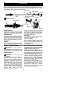
TOOLS REQUIRED
S Hex wrench (provided)
INSTALL ING PR UNER ATTACH-
MENT
CAUTION:
When removing or installing at-
tachments, place the uniton a f lat surface for
stability.
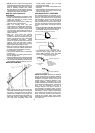
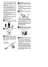
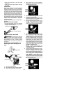
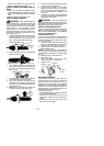
1. Loosen the coupler by t u rning the knob
counterclockwise.
Coupler
Knob
LOOSEN
TIGHTEN
Shipping
protector
2. Remove shipping protector fromcoupler.
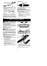
3. Removethe shaftcap fromthe prunerat-
tachment (if present).
4. Position locking/release button ofattach-
ment into guide recess of coupler.
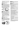
5. Pushtheattachment intothe coupleruntil
the locking/release button snaps into the
primary hole.
6. Beforeusing theunit,tightentheknobse-
curely by turning clockwise.
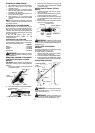
Coupler Primary Hole
Upper
Shaft
Locking/
Release
Button
Lower
Attachment
Guide Recess
WARNING: M ake s ure the locking/
release button is locked in the primary hole
and theknob is securely tightened before op-
eratingthe unit. Allattachments aredesigned
to be used in the primary hole.
For optional attachments, see the AS-
SEMBLY section of the applicable attach-
ment instruction manual.
SHOULDER STRAP ASSEMBLY
WARNING: Proper shoulder strap
adjustments m ust be made with the engine
completely s topped before using unit.
1. Try on shoulder strap and adjust for fit
and b alance beforestarting theengine or
beginning a cutting operation.
2. Insert your right arm and head through
the shoulder strap and allow it to rest on
your left shoulder. Make sure the danger
sign is centered on your back and the
hook is to the right side of your waist.
NOTE: A one-half twist is built in the shoul-
der strap to allow the s trap to r est flat on the
shoulder.
3. Adjust the strap, allowing the hook to be
about 3 -- 6 inches below the waist.
4. Fasten the strap hook to the clamp lo-
cated b etweenthethrottlehandleandthe
assist handle and lift the tool to the oper-
ating position.
NOTE: It may be necessary to relocate the
shoulder strap clamp on the s haft for proper
balancing of unit.
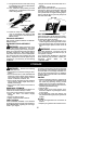
TO RELOCATE SHOULDER ST RAP
CLAMP:
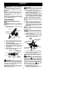
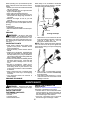
1. Loo sen and remove both clamp screws.
2. Place the upper shoulder strap clamp
over the upper shaft.
3. Position the low er shoulder strap clamp
under theupper shaft andalign theupper
and lower clamp screw holes.
Upper Shoulder
Strap Clamp
Screws
Lower Shoulder
Strap Clamp
POWERHEAD
END
ATTACHMENT
END
4. Insert two screws into the screw holes.
5. Secure shoulder strap clamp by tighten-
ing screws with a hex wrench.
ADJUSTING THE ASSIST HANDLE
WARNING: When adjusting the as-
sist handle, be sure it remains between the
coupler and the
lower arrow (closest t o
coupler) on the safety label to ensure proper
balancing of unit. When adjus ting the assist
handle orhandlebar during useof optionalat-
tachments, it must be repositioned between
the throttle trigger and the
upper arrow
(closest to engine) on the safety label.
1. Loo sen wing nut on handle.
2. Rotate the handle on the shaft to an up-
right position; retighten wing nut.