


4
ASSEMBLY
WARNING:
If received assem bled, re-
peat all steps to ensure your unit is proper ly as-
sembled and all fasteners are secur e.
Examine parts for damage. Do not use dam-
aged parts.
NOTE:
If youneedassistanceor findthat parts
are missing or damaged, call 1-800-554-6723.
TOOLS REQUIRED
S
Hex wrench (provided)
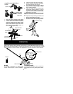
HANDLEBAR ASSEMBLY
DANGER:
RISK OFCUT. Toavoidse-
rious injury, the barrier portion of the handle-
bar must be installed as shown on the upper
tube of the powerhead to provide a barrier be-
tweenoperator andthespinning blade. Attach
tube clamp above arrowonsafety warning de-
cal onthe upper tube (powerhead end of unit).
Ensure handlebar is positioned on handlebar
clamp between the arrows on the handlebar
decal.
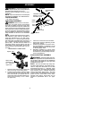
NOTE:
The tubeclamp basehas fourspacer
tabs attached. These tabs are provided to
adapt this attachment for use wi th power-
heads that have a1
"
diameter upper tube (the
tube clamp will not tighten down securely on
the1
"
diameter upper tubewithout usingthese
spacer tabs). The tabs must be broken off
completely before use and placed over the
screw holes on the clamp base. These tabs
arenot needed forpowerheads with a7/8
"
up-
per tube.
Spacer Tabs
HANDLEBAR CLAMP BASE
Spacer Tabs
positioned for use
on 1
"
diameter
upper tube
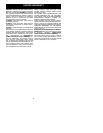
1. Place the tube clamp over the upper tube
above the arrow on the safety decal.
2. Position the clamp base under the upper
tube and align the tube clamp and clamp
base screw holes (use spacer tabs be-
tween tube clamp and clamp base if nec-
essary to secure clamp, i.e. for1
"
diame-
ter upper tube).
POWERHEAD
END
A TTACHMENT
END
Screws
Clamp
Base
Handlebar Clamp
between arrows on
handlebar decal
Clamp
Knob
Tube
Clamp
Handlebar
Arrow on
Safety Decal
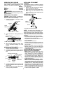
3. Insert four screws into the screw holes.
4. Secure tube clamp by tightening screws
with the hex wrench.
5. Position the handlebar as shown, ensur-
ing the handlebar is positioned on the
handlebar clamp between thetwoarrows
on the handlebar decal.
6. Retighten handlebar by turning clamp
knob clockwise until handlebar is secure
and stationary in clamp (clamp knob can-
not be overtightened).
SHOULDER STRAP ASSEMBLY
WARNING:
Proper shoulder strapand
handlebar adjustments are required before use.
The shoulder strap clamp m ust be installed as
shown above the handlebar on the upper tube
(pow erhead end of unit).
NOTE:
The lower shoulder strap clamp has
twospacertabsattached. Thesetabs arepro-
vided to adapt this attachment for use with
powerheads that have a 1
"
diameter upper
tube (the shoulder strap clamp will not tighten
down securely on the 1
"
diameter upper tube
without using these s pacer tabs). The tabs
must be broken off completely before useand
placed over the screw holes on the lower
shoulder strap clamp. These tabs are not
needed for powerheads with a 7/8
"
upper
tube.