


14
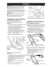
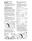
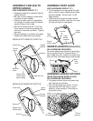
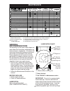
ASSEMBLE CABLE(S) TO
UPPER HANDLE
(USE HARDWARE GROUP “F”)
• Assemble cable(s) to opposite side of
upstop bracket.
• Be sure to route cable(s) underneath
crossbar of lower handle.
• Position throttle control (if equipped)
on outside of handle and zone control
square fi tting on the inside.
• Secure to handle with the 1/4-20 ma-
chine screw or hex bolt supplied and
lock nut (if required) as shown. Tighten
se cure ly.
• Secure cable(s) to crossbar and low er
handle with cable tie(s) as needed.
Throttle
control
Machine
screw
Control bar
Locknut
Wire tie
Engine zone
control cable
square fi tting
Upstop
bracket
Upper
handle
Control bar
Engine zone
control cable
Up-stop
bracket
Wire tie
Screw
MODELS WITH REMOTE THROTTLE:
MODELS W/O REMOTE THROTTLE:
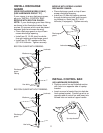
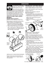
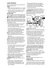
ASSEMBLE ROPE GUIDE
(USE HARDWARE GROUP “G”)
• Put threaded end of rope guide through
hole in side of upper handle above lower
handle crossbar. Se cure with 1/4-20
keps locknut.
• Hold control bar against upper handle
and slowly pull starter rope out until rope
will slip into loop of rope guide.
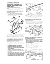
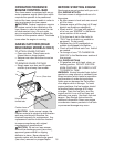
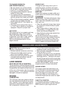
SPARK PLUG BOOT (IF EQUIPPED)
(NO HARDWARE REQUIRED)
On some model lawn mowers a spark plug
boot is packed loose in the parts bag. If
your model has one, install it on spark plug
wire and then reconnect plug to spark plug.
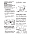
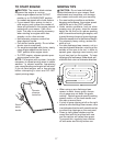
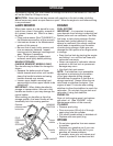
ASSEMBLE GRASS CATCHER
(REAR DISCHARGE MODELS ONLY)
(NO HARD WARE REQUIRED)
• Put grass catcher frame into grass bag
with rigid part on bottom.
• Slip vinyl bindings over frame. If bind-
ings are too stiff, hold them in warm
water for a few minutes. Allow bag to
dry before using.
Boot
Spark
plug
wire
Upper
handle
Engine
starter rope
Rope
guide
Locknut
Lower
handle
crossbar
Frame
handle
Frame
opening
Vinyl
bindings