


7
02085
02342
02335
ALIGNMENT
MARKS
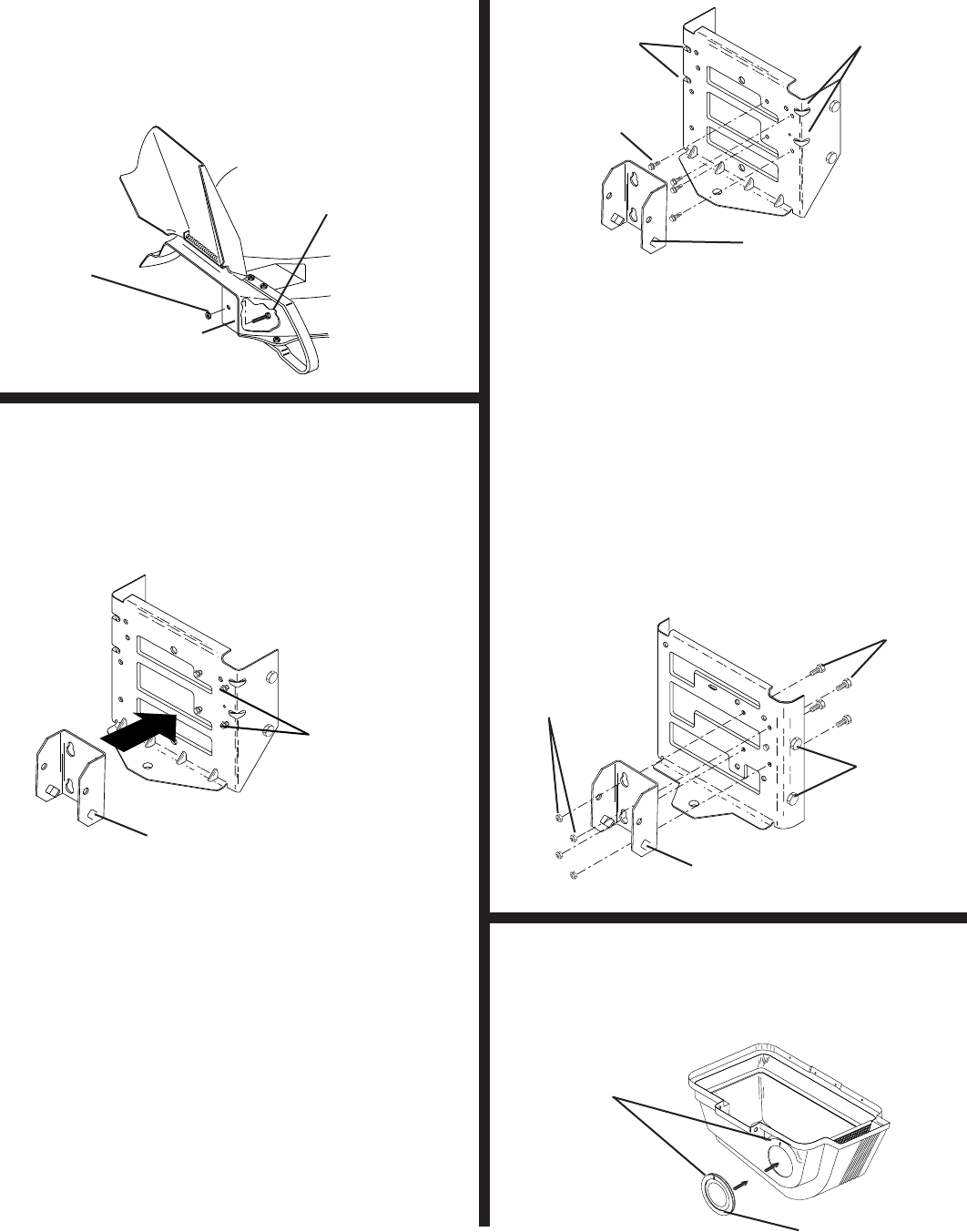
COVER SEAL
FIG. 3
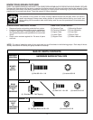
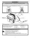
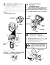
COVER SEAL (See Fig. 3)
No hardware required
1. Align mark on seal with mark at cover opening.
2. Work seal into opening so cover sits between fl anges
of seal.
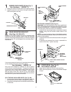
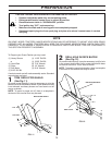
MOWER DECK BAFFLE (See Fig. 1)
Use Hardware - - GROUP "A"
1. Raise your tractor mower deck to its highest position.
2. Install the hex bolt, and locknut through mower deck
baffl e and tighten securely.
HEX BOLT
LOCKNUT
MOWER DECK BAFFLE
FIG. 1
1
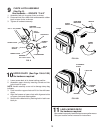
BOLTS AND LOCKNUTS (See Fig. 2C)
IMPORTANT: ON TRACTORS WITH FUEL TANK UNDER THE
SEAT, THE DRAWBAR MUST BE REMOVED FOR INSTALLATION
OF MOUNTING BRACKET. TO REMOVE DRAWBAR, REMOVE
TWO HEX BOLTS ON BOTH SIDES OF DRAWBAR.
1. Assemble the mounting bracket, lanced tabs towards
bottom, using the four smaller inside holes on the
drawbar.
NOTE: If your tractor drawbar does not have the four correct
holes for mounting the bracket, refer to the PREP A RA TION
sec tion of this man u al.
2. Install the four bolts and locknuts as shown and tighten
securely.
3. If drawbar was removed from tractor, reassemble to
tractor at this time. Tighten securely.
DRAWBAR
MOUNTING
BOLTS
(BOTH SIDES)
LANCED TABS TOWARD BOTTOM
BOLTS
LOCKNUTS
FIG. 2C
3
2
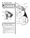
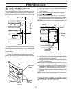
REAR MOUNTING BRACKET
(See Figs. 2A, 2B & 2C)
NOTE: If your tractor already has four (4) shoulder bolts
installed on the rear draw bar, simply hang the mounting
bracket, lanced tabs towards bottom, on the bolts. Discard
hardware group "B" and disregard the remaining Step 2
instructions.
LANCED TABS
TOWARD BOTTOM
0
2
3
3
7
SHOULDER
BOLTS
FIG. 2A
If your tractor does not have four (4) shoulder bolts installed
on the drawbar, follow the instructions below.
Use Hardware - - GROUP "B"
Only one set of hardware in GROUP "B" will be used to
mount the rear mounting bracket. To determine which set
is correct for your tractor, check to see if there are (2) two
upper corner ribs on each side of drawbar. If your tractor
has the upper corner ribs, use the (4) four self tapping
shoulder bolts. If your tractor does not have the corner ribs,
use the set of (4) four bolts and locknuts.
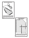
SELF TAPPING SHOULDER BOLTS (See Fig. 2B)
1. Using the four formed holes in the drawbar, install the
four shoulder bolts as shown and tighten securely.
2. Hang the mounting bracket, lanced tabs towards bottom,
on the bolts.
02
3
3
6
UPPER CORNER
RIBS
UPPER CORNER
RIBS
SELF
TAPPING
SHOULDER
BOLTS
FIG. 2B
LANCED TABS
TOWARD BOTTOM