


10
W
A
RN
IN
G
D
o
n
o
t
o
p
e
r
a
t
e
m
o
w
e
r
u
n
l
e
s
s
c
o
n
t
a
i
n
e
r
i
s
p
r
o
p
e
r
l
y
i
s
n
s
t
a
l
l
e
d
.
C
o
n
t
a
i
n
e
r
i
s
s
u
b
j
e
c
t
t
o
w
e
a
r
a
n
d
d
e
t
i
e
r
i
o
r
a
t
i
o
n
.
C
h
e
c
k
b
a
g
f
r
e
q
u
e
n
t
l
y
.
R
e
p
l
a
c
e
w
h
e
n
c
r
a
c
k
e
d
o
rd
a
m
a
g
e
d
.
U
s
e
o
n
l
y
a
r
e
c
o
m
m
e
n
d
e
d
r
e
p
l
a
c
e
m
e
n
t
c
o
n
t
a
i
n
e
r
.
W
A
R
N
IN
G
D
o
n
o
t
o
p
e
r
a
t
e
m
o
w
e
r
u
n
l
e
s
s
c
o
n
ta
i
n
e
r
i
s
p
ro
p
e
r
l
y
i
s
n
s
t
a
l
l
e
d
.
C
o
n
t
a
i
n
e
r
i
s
s
u
b
j
e
c
t
t
o
w
e
a
r
a
n
d
d
e
t
i
e
r
i
o
r
a
t
i
o
n
.
C
h
e
c
k
b
a
g
fr
e
q
u
e
n
tl
y
.
R
e
p
l
a
c
e
w
h
e
n
c
r
a
c
k
e
d
o
r
d
a
m
a
g
e
d
.
U
s
e
o
n
l
y
a
r
e
c
o
m
m
e
n
d
e
d
r
e
p
l
a
c
e
m
e
n
t
c
o
n
t
a
i
n
e
r
.
0
2
3
4
4
W
A
R
N
IN
G
D
on
o
to
p
e
r
a
temow
e
r
u
nl
e
s
s
c
o
nt
a
i
n
e
r
i
s
p
r
op
e
r
l
y
i
s
n
s
t
a
l
l
ed
.
C
on
t
a
i
n
e
r
i
s
s
u
bj
ec
tt
o
w
e
a
r
a
ndd
et
i
er
i
o
ra
t
i
o
n
.
C
h
ec
k
b
agf
r
e
q
u
en
t
l
y
.
R
ep
l
a
c
ew
h
e
n
c
r
a
c
k
edo
r
d
a
ma
ge
d
.
U
s
e
on
l
y
ar
e
c
o
mme
n
d
edr
e
p
l
a
c
e
me
n
tc
o
n
t
a
i
n
e
r
.
W
A
R
N
I
N
G
D
o
n
ot
o
p
er
at
e
m
o
w
er
un
l
e
s
s
c
o
n
t
a
i
n
er
i
s
p
r
o
p
e
r
l
y
i
s
n
s
t
a
l
l
e
d
.
C
o
n
t
a
i
ne
r
i
s
s
u
bj
e
c
t
t
ow
ea
ran
dde
t
i
e
r
i
o
r
a
t
i
on
.
C
he
c
k
b
ag
f
r
e
q
ue
n
t
l
y
.
R
e
pl
a
c
e
w
h
en
c
ra
c
k
e
d
or
d
a
m
a
g
e
d
.
U
s
e
o
nl
y
a
r
e
c
o
mm
e
nd
edr
e
p
l
ac
e
m
e
n
tc
o
n
t
a
i
n
e
r
.
02
345
11
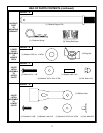
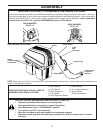
LEVEL MOWER DECK
No hardware required
Be sure deck is properly leveled for best mower per for man ce.
See your tractors owner's manual for ins truc tions.
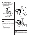
10
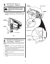
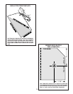
UPPER CHUTE (See Figs. 10A & 10B)
No hardware required
1. Lower mower deck to its lowest cutting position.
2. Assemble upper chute by inserting curved end into
hole in back of cover.
NOTE: Handle carefully so as not to damage dump bag
indicator.
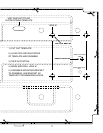
3. Push in and turn upper chute until it is in line with lower
chute.
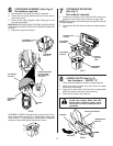
4. Align the bosses on lower chute with alignment slots
on upper chute and slide together.
5. Secure with rubber latch by hooking hole in latch over
latch pin.
LOWER
CHUTE
COVER
DUMP BAG
INDICATOR
UPPER
CHUTE
HANDLE
FIG. 10A
RUBBER
LATCH
ALIGNMENT
SLOTS
BOSSES
LATCH PIN
FIG. 10B
0
2102
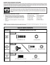
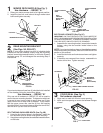
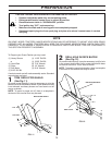
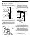
CHUTE LATCH ASSEMBLY
(See Fig. 9)
Use Hardware - - GROUPS "F & G"
1. Assemble latch pin to upper chute, as shown.
2. Press weld nut into rubber latch and assemble rubber
latch to lower chute, as shown.
3. Tighten all hardware securely.
FIG. 9
ACORN NUT
RUBBER
LATCH
WELD
NUT
LOCK WASHER
#10 x 5/8"
SCREW
LOWER CHUTE
UPPER CHUTE
WASHER
3/16 x 3/4 x 16 Ga.
WASHERS
3/16 x 3/4 x 16 Ga.
SPLIT
SPACER
#10 x 1-1/8" SCREW
9