


14
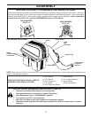
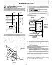
DRILL 4 HOLE BOLT PATTERN
(See Figs. 13,14 & 15)
On some model tractors, it may be necessary to drill new
holes in drawbar for the mounting bracket. To determine if
you need to drill holes in your drawbar, closely look at the
illustration below.
Your drawbar may or may not have some or all of the holes
shown. For the assembly of your new grass catcher only the
fi ve holes dimensioned will be used. If your drawbar does
not have the fi ve holes in the correct po si tions continue
with this section.
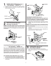
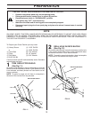
1. Remove the drawbar by removing the two mounting
bolts on each side. Keep hardware for remounting.
NOTE: If your tractor has a wire loop mounted to the draw-
bar, remove it at this time.
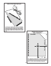
2. Place the drawbar in a vice or similar locking device.
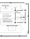
3. Cut out the 4 hole bolt pattern template from the back
of this manual.
4. Align top and right edge of template and drawbar.
5. Tape in position.
6. Mark and drill hole #1 only, using a 11/32" drill bit.
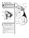
7. Assemble mounting bracket to drilled hole in drawbar
with one hex bolt and nut from hardware group "B".
NOTE: Mounting bracket must be assembled with lanced
tabs to bottom as shown.
8. Align bracket so it is parallel with right edge of drawbar
and tighten securely. Holes in bracket should line up
with remaining holes in template.
9. Using bracket as a template, drill remaining three (3)
11/32" mounting holes.
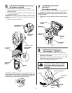
NOTE: If your tractor is equipped with a wire loop, drill new
mounting hole as shown, if necessary.
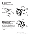
10. For ease of assembly mounting bracket should be
assembled at this time (refer to "REAR MOUNTING
BRACKET" in ASSEMBLY section of this manual).
11. Remount drawbar to tractor using hardware previously
removed.
NOTE: Failure to reconnect the wire loop connection will
result in not being able to start tractor.
02350
02349
PREPARATION
HEX BOLT
AND NUT
DRAWBAR
MOUNTING
BRACKET
WIRE LOOP
MOUNTING
HOLE
(drill 9/32"
if necessary)
PARALLEL
LANCED TABS
TO BOTTOM
FIG. 15
PROCEED WITH ASSEMBLY INS TRUC TIONS
IN THE FRONT OF THIS MANUAL
FIG. 13
DRAWBAR
FIG. 14
DRAWBAR
MOUNTING
BOLTS
(both sides)
WIRE LOOP
(Not on all
models)
3
1-1/8"
2-3/4"
2-1/4"
3-3/8"
2"
1-7/16"
02348