


11
4. Pull st arter rope handle sharply until en-
gine starts and runs.
5. Allow unit to run for 10--15 seconds, then
fully squeeze the throttle trigge r to disen-
gage the starting system.
STARTING A WARM ENGINE
1. Squeeze and hold the throttle trigger .
Keep throttle trigger fully squeezed until
engine runs smoothly.
2. Pullstarter rope sharply w hile squeezing
throttle trigger until engine runs.
NOTE: Normally, the warm starting proce-
dure can be used within 5--10 minutes after
the unit is turned off. If the unit sits for more
than 10 minutes without being ran, it will be
necessary to start the unit by following the
steps under ST AR TING A COLD ENGINE or
following the starting instruction steps shown
on the unit.
START ING A FLOODED ENGINE
Flooded engines can be start ed by placing
the start lever to the RUN position. Fully
squeeze thrott le trigger. Pull the starter han-
dle repeatedly whilesqueezingthrottletrigger
until engine starts and runs. This could re-
quire pulling the st arter handle many times,
depending on how badly the unit is flooded.
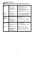
If the unit still doesn’t start, refer to
TROUBLESHOOTING TABLE or call
1-800-554-6723.
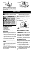
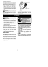
OPERATING THE COUPLER
This mode l is equipped with a coupler which
enables optional attachments to be installed.
The optional attachments are:
MODEL:
Edger PP1000E......................
Cultivato r PP2000T...................
Blower PP3000B.....................
Brush cutter PP4000C.................
Pruner PP5000P.....................
WARNING: Alwaysstopunit anddis-
connect s park plug beforeremoving orinstal-
ling attachments.
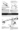
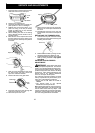
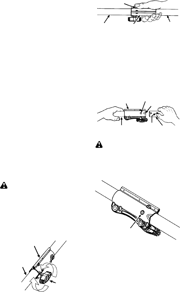
REMOVING TRIMMER ATTACH-
MENT (OR OTHER OPTIONAL AT-
TACHMENTS)
CAUTION:
When removing or installing at-
tachments, place the unit on aflat surface for
stability.
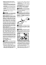
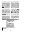
1. Loosen the coupler by turning the kn ob
counterclockwise.
Attach m ent
Coupler
Knob
LOOSEN
TIGHTEN
2. Press a nd hold t he locking/ release button.
Locking/Release
Button
Coupler
Upper Shaft
Attachment
3. While secu rely holding the engine and
upper shaft, pull the attachment straight
out of the coupler.
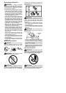
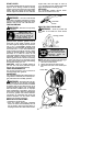
INSTALLING OPTIONAL ATTACH -
MENTS
1. Remove the shaft cap from the attach-
ment (if present).
2. Position locking/releasebuttonof attach-
ment into guide recess of coupler.
3. Pushtheattachmentintothe coupleruntil
the locking/release button snaps into the
primary hole .
4. Before usingthe unit, tightenthe knobse-
curely by turning clockwise.
Coupler
Primary Hole
Upper
Shaft
Locking/
Release
Button
Attachment
Guide Recess
WARNING: Make su re the locking/
release button is locked in the primary hole
and the knob is s ecurely tightened before op-
erating the unit. All atta chme nts are des igned
to be used in the p rimary hole unless otherwise
stat ed in the applicabl e attachment instruction
manual. Usingthe wrong h ole could l ead toseri-
ous inj ury or d am age to the u nit.
Locking/Release
Button in Primary Hole
OPE RATING INS TRUCTIONS
It i s recommended that t he engine not be
operated for longer than 1 minute at full
throttle.