


3-6
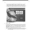
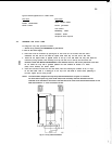
6. Change the filament voltage supply, if necessary, depending on the type of focus.
A fine focus tube should have a filament voltage of 8 volts, and broad and normal focus tubes require
10 volts. On later tubes the type of focus is indicated, and in other cases consult the tube instruction card.
To change the filament voltage, switch off the unit, open the right-hand side panel by loosening the two
Allen screws.
The panel is hinged at the bottom. Behind the front panel is a switch marked BF (broad focus) and
NF FF (normal/fine focus). Select as required.
Close the cover.
7. Close the air inlet valve, and turn on the water supply.
8.
Turn the
kV
and
mA
controls to the minimum position, and operate the GENERATOR I push-button.
9. When an X-ray tube is new, or has not been used for a week or more, the following procedure should be
followed:
Check that the mA meter reading is stable, then slowly increase the
kV
control to 30
kV,
over a period
of one minute. Slowly increase the mA control watching for signs of instability of the
mA
reading.
DO NOT EXCEED THE RATED
kV
AND
mA
VALUES, as shown in Appendix 1; disregard the instruction
card values (X-ray diffraction tubes).
Slowly increase the
kV
to the required operating high-voltage, at the same time adjusting the
mA
reading
so that the maximum power to the tube does not exceed the rated limits. If the
mA
meter reading shows
any sign of instability the
kV
should be reduced, and held at a lower value for about a minute before
attempting to advance the
kV
control again.
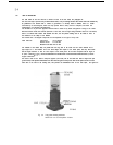
3.7. POSITIONING THE TUBE SHIELD
The tube shield can be placed in one of three orientations on top of the generator, i.e. so that the X-ray
beams make angles of either
90°
or 45° or 0° to the front of the generator.
However, the rotation of the tube shield must not be more than
90°
in either direction from its original
position. Since the line and point focus beams are
90°
apart it is possible to place the tube shield with either
beam in any position depending on the use of the generator, or personal preference.
The tube shield is fixed to the table top by means of four Allen screws. Remove the screws and rotate the tube
shield carefully, simultaneously ensuring that the cables and water hoses inside the cabinet are not unduly
tensioned. For this purpose open the left-hand side panel of the generator cabinet, and observe the hoses and
cable. Refix the tube shield on the table top with the screws, and close the side panel.
3.8.
DIFRACTOMETRY
OPERATION
The generator will normally be used to obtain the simultaneous (photographic) registration of reflections from
a specimen, therefore, stabilisation of the X-ray tube voltage is not necessary.
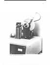
A PE 1612 a.c. voltage stabiliser can be used in the mains supply to the generator, when an improved stabilisation
is required for more accurate powder diffractometry.
This voltage stabiliser is specially designed to provide a stable mains voltage to small units, such as the PW 1720
X-ray generator. Variations in the mains voltage from
-15% to + 10% will be stabilised so that the output
voltage variation is better than
0,1%.
A full specification is given in the operation manual of the PE 1612 a.c.
voltage stabiliser.
A PW 1050 vertical goniometer with stepping motor or with synchronous motor can be installed on top of the
generator, and two mounting holes are provided in the top cover, see figure 3.4. Refer to the PW 1349
“Diffractometer kit” instruction manual, for alignment information.