


Assembly / Installation 4
IMPORTANT: To prevent leaks, be sure that the cleats on
the corners of the basin gasket are up with the cover
upside down (that is, not pressed into the sealing face of
the cover).
Step 7 (See Figure 5)
Push the screws with their washers installed up through
the holes in the rim of the cover and in the basin gasket
(the cover will retain the screws).
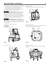
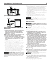
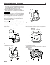
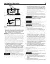
Step 8 (See Figure 6)
• Align the cover with the discharge pipe and cords.
• Pull the cords through the non-threaded hole in the
basin cover.
• Place the cover over the discharge pipe.
• Install the cords in the cord grommet
• Install the cord/grommet assembly in the non-threaded
hole in the basin cover; don’t pull the cords tight.
Step 9 (See Figure 6)
Fasten the basin cover to the basin with the capscrews
previously inserted in the cover (Step 7).
IMPORTANT: To prevent leaks, be sure the locating cleats
on the corners of the basin gasket are outside the edges of
the basin rim, not pressing against the rim.
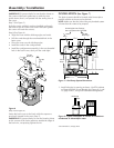
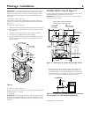
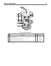
INSTALLATION (See Figure 7)
The basin (system) should be located at the lowest place
possible relative to the area to be drained.
NOTE: Make sure that the inlet of the pre-plumbed system
is lower than the water to be pumped.
1. Install inlet pipe in opening as shown. Use RTV sealants
or Plasto-Joint Stik* to seal threads. See Figures 8, 9, and
10, page 4 and 5, for typical installation arrangements.
*Lake Chemical Co., Chicago, Illinois
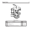
1 " NPT
Discharge
Thread pipes into fittings;
don't go past end of threads.
1 " NPT
Inlet
15
1
/
8"
13
3
/
4"
12"
12"
Vertical Float Switch
1/3 HP
Pump
1 " NPT
Vent
1
2
1
2
1
2
Figure 7 – Sink Pump System Dimensions
4720 1004
Pump
Inlet
1 " NPT
Vent
Cord Grommet
1 " NPT
Discharge
Discharge
1
2
1
2
Figure 6
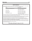
Discharge
Vent
Pump
Figure 8 – Typical installation to remove air conditioner
condensate or dehumidifier water