


6
Tighten or loosen belt until:
d = 0.016 X L
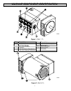
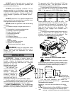
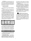
If the control box is not located on the correct
side for your application, it can be rotated to the
opposite side. First remove the fan vents, than
remove the four drive end bracket bolts. Rotate the
drive end bracket 180°, re-torque bolts to 17 ft•lb.
Reinstall the fan vents. Remove the four screws at the
base of control box, rotate the control box 180°. The
voltmeter is now on the back of the machine instead of
the front. See below for terminology.
DANGER Remember, exhaust fumes are
deadly carbon monoxide gas, and must be vented to
the outside where there are no people. Cooling air of
sufficient amounts must be brought in and exhausted
out to ensure proper cooling of the engine and
generator.
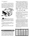
If you desire to direct couple the generator to an
engine, great care must be taken to align the shaft of
the generator and engine to within the specified
tolerances of the chosen coupler.
NEVER install your generator inside confined
areas. Inside installation can cause health hazards or
death.
LOAD APPLICATION
It is important to determine the total electrical load
before it is connected to the generator. The two major
factors in determining the life of a generator head are:
heat build up, caused by overloading the generator
and corrosive contaminants, that attack the wiring
insulation. If the generator is overloaded, the wires
become excessively hot and cause the insulation to
break down, reducing its ability to resist corrosive
contaminants. Over time the effectiveness of the
insulation is eliminated and a dead short can result.
Always compare the generator nameplate data
with that of the equipment to be used to ensure that
watts, volts, amperage, and frequency requirements
are suitable for operating equipment. The wattage
listed on the equipment nameplate is its rated output.
However, some equipment may require three to ten
times more wattage than its rating on the nameplate,
as the wattage is influenced by the equipment
efficiency, power factor and starting system. NOTE: If
wattage is not given on equipment nameplate,
approximate wattage may be determined by
multiplying nameplate voltage by nameplate
amperage.
VOLTS X AMPS = WATTS
Example: 120V X 5A = 600W
When connecting a resistive load such as
incandescent lights, heaters or common electric power
tools, a capacity of up to the generator full rated
wattage output can be used.
When connecting a resistive-inductive load such
as a fluorescent or mercury light, transformers or
inductive coils, a capacity of up to 0.6 times the
generator’s full rated output can be used.
Always allow the generator to reach operating
speed before a load is applied.
STARTING ELECTRIC MOTORS
Electric motors require much more current (amps)
to start than to run. Some motors, particularly low cost
split-phase motors, are very hard to start and require 5
to 7 times more current to start than to run. Capacitor
motors are easier to start and usually require 2 to 4
times as much current to start than to run. Repulsion
Induction motors are the easiest to start and require
1.5 to 2.5 times as much to start than to run.
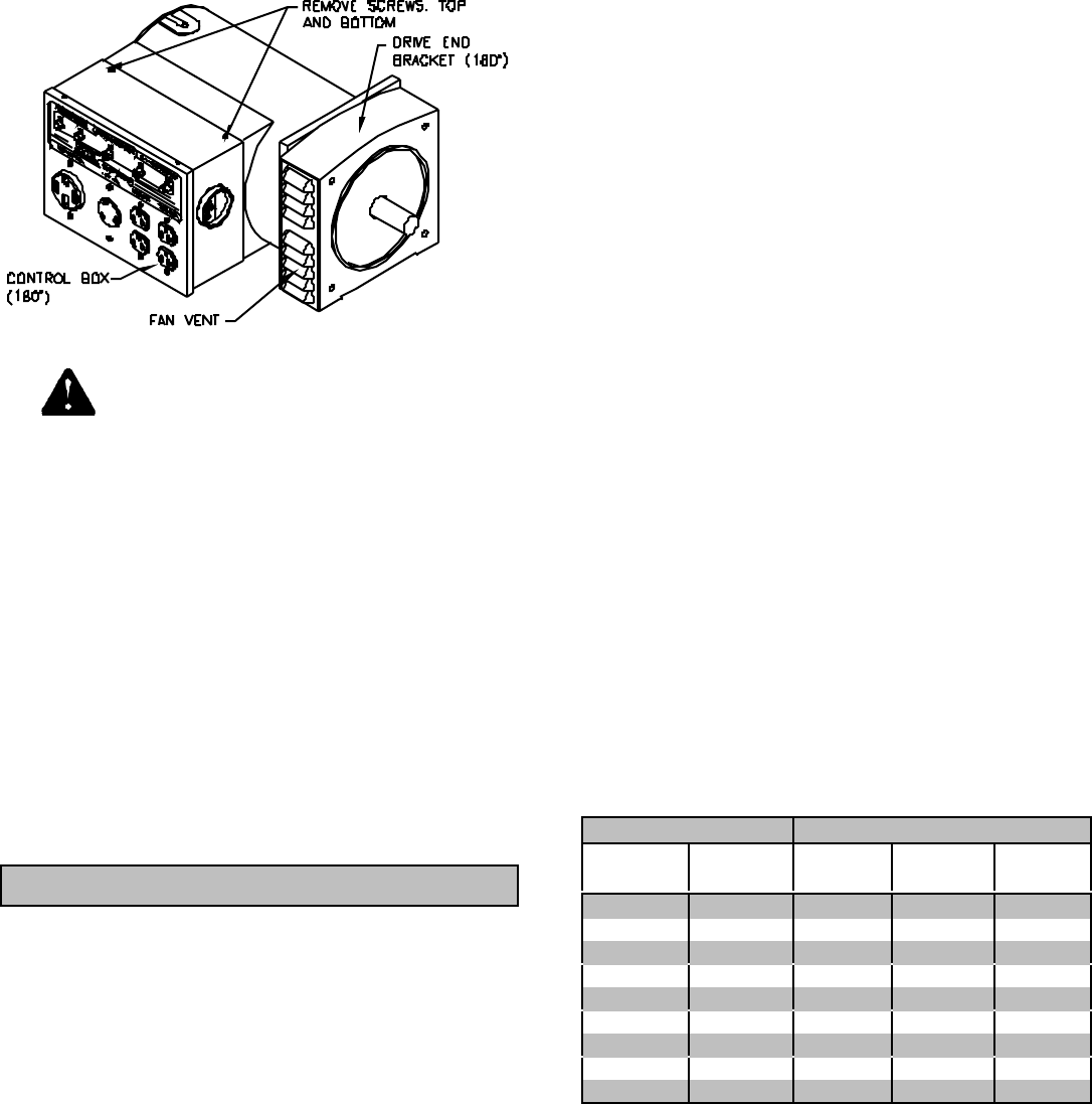
Most fractional motors take about the same
amount of current to run them whether they are of
Repulsion-Induction (RI), Capacitor (Cap), or Split-
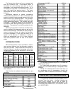
Phase (SP) type. The following chart shows the
approximate current required to start and run various
types and sizes of 120 volt 60 cycle electric motors
under various conditions.
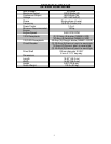
120V, 60 Hz Motors
Starting Amps
Hp motor Running
Watts
RI type Cap type SP type
1/6 525 7-11 9-18 16-22
1/4 700 9-15 12-23 22-32
1/3 875 11-18 14-29 26-35
1/2 1175 15-25 20-40 NA
1 1925 24-40 32-64 NA
1 1/2 2400 30-50 40-80 NA
2 2900 36-60 48-96 NA
3 4075 51-85 68-136 NA
5 6750 84-140 112-224 NA
00298