


Machine Component Identification - Item #165957K
9
REFERENCE GUIDE
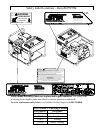
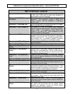
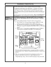
Reference 1 – Circuit Breakers This portable single phase generator has 1, 15 amp (A)
2, 20A, and 2, 30A push to reset circuit breakers to
protect against electrical overloads.
Reference 2 – 120/240V
Receptacle
The locking device is a 120/240V 30A NEMA L14-30R
receptacle. This receptacle accepts a NEMA plug
number L14-30P. Use this receptacle if installing a
transfer switch.
Reference 3 – Grounding Post Ground the generator via the grounding post, to a copper
pipe or rod that is driven into moist soil.
Reference 4 – 120V Receptacle The duplex is a 120V 20A straight blade receptacle,
National Electrical Manufacturer’s Association (NEMA)
number 5-20R. This receptacle accepts NEMA plug
numbers 5-15P and 5-20P. Each receptacle on this
duplex is capable of drawing 20A.
Reference 5 – 120V Receptacle The duplex is a 120 volt (V) 15 amp (A) straight blade
receptacle, National Electrical Manufacturer’s Association
(NEMA) number 5-15R. This receptacle accepts NEMA
plug number 5-15P. The duplex is capable of drawing
15A out of either receptacle or a combination of both.
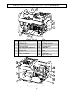
Reference 6 – Oil Drain Plug Refer to your Honda engine manual for oil change
recommendations.
Reference 7 – Air Cleaner Refer to your Honda engine manual for air cleaner care.
Reference 8 – Super Silent
Muffler
4 dB less than Honda’s standard muffler.
Reference 10 – Gas Cap with
Gauge
The gas cap is extra large, creating a large hole for
refilling and a comfortable grip. You can monitor the fuel
level without removing the cap by using the fuel level
indicator built into the gas cap.
Reference 11 – 6.5 Gallon Gas
Tank
Large tank allows for extended run capabilities. Always
allow room for gasoline expansion by not filling the gas
tank completely full.
Reference 12 – Generator Head The electricity producing part of the generator.
Reference 13 – Battery Box The battery box provides protection for the battery and will
accept a standard lawn tractor size battery (Group U1-7).
See battery section for sizing.
Reference 14 – Vibration Isolation
Mounts
The engine and generator are mounted on rubber
cylinders that absorb most of the engine vibration. This
feature eliminates the tendency of the machine to “walk”
which is common in engine powered equipment.
Reference 15 – Recoil Grasp firmly when starting engine. Consult engine
manual for further instruction.
Reference 16 – Fuel Valve Lever The engine has an ON-OFF valve mounted on the front
of the engine. Always keep this valve closed when the
generator is not in use.
Reference 17 – Choke Lever Used during cold starts. Refer to the starting/stopping
instructions and the Honda engine owner’s manual for
further instruction.
Reference 18 – Engine Key
Switch
The engine key is located on the engine. Always locate
this switch and be familiar with its location before
operating the generator. Consult the Honda engine
owner’s manual for further instructions.