


4
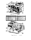
GENERATOR FEATURE
Reference 1 - Air Cleaner. Refer to your Honda
engine manual for air cleaner care.
Reference 2 - Starting/Stopping Instructions.
Reference 3 - Oil Drain Plug. Refer to your Honda
engine manual for oil change recommendations.
Reference 4 - Control Panel. See Fig. 3 for details.
Reference 5 - Gas Cap with Gauge. The gas cap is
extra large, creating a large hole for refueling. You can
monitor the fuel level without removing the cap by using
the fuel level indicator built into the gas cap.
Reference 6 - 6.5-Gallon Gas Tank. Large tank
allows for extended run capabilities. ALWAYS all ow room
for gasoline expansion by not filling the gas tank
completely full.
Reference 7 - Super Silent Muffler. 4 dB less than
Honda’s standard muffler.
Reference 8 - Generator Head. The electricity
producing part of the generator.
Reference 9 - Battery Box. Warning: Always wear
safety glasses when working on or near the battery.
The battery box provides protection for the battery and will
accept a standard lawn tractor size battery (Group U1-7).
The engine requires a 12-volts battery, with a minimum
rating of 18Ah (Amp-Hour). When installing the battery,
always connect the red colored (“positive” or “+”) cable
first. When disconnecting the battery, always remove the
black colored (“negative” or “-”) cable first.
WARNING Sulfuric acid is a corrosive poison.
Avoid contact with skin, eyes or clothing. Always wear
safe ty gl asse s.
Reference 10 - Vibration Isolation Mounts. The
engine and generator are mounted on rubber cylinders
that absorb most of the engine vibration. This feature
eliminates the tendency of the machine to “walk” which is
common in engine powered equipment.
Reference 11 - Recoil. Grasp firmly when starting
engine.
Reference 12 - Gas Line Valve. The engi ne is
equipped with an ON-OFF valve located on the left side of
the recoil. ALWAYS keep this valve closed when the
generator is not in use.
Reference 13 - Choke Lever. Used during cold
starts. Refer to the starting/stopping instructions and the
Honda engine manual for usage.
Reference 14 - Electric Start/Stop Switch. The
engine key is located on the engine. Always locate this
switch and be familiar with its location before operating the
generator.
Reference 15 and 16 – Reserved for future use.
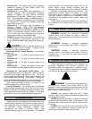
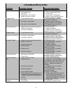
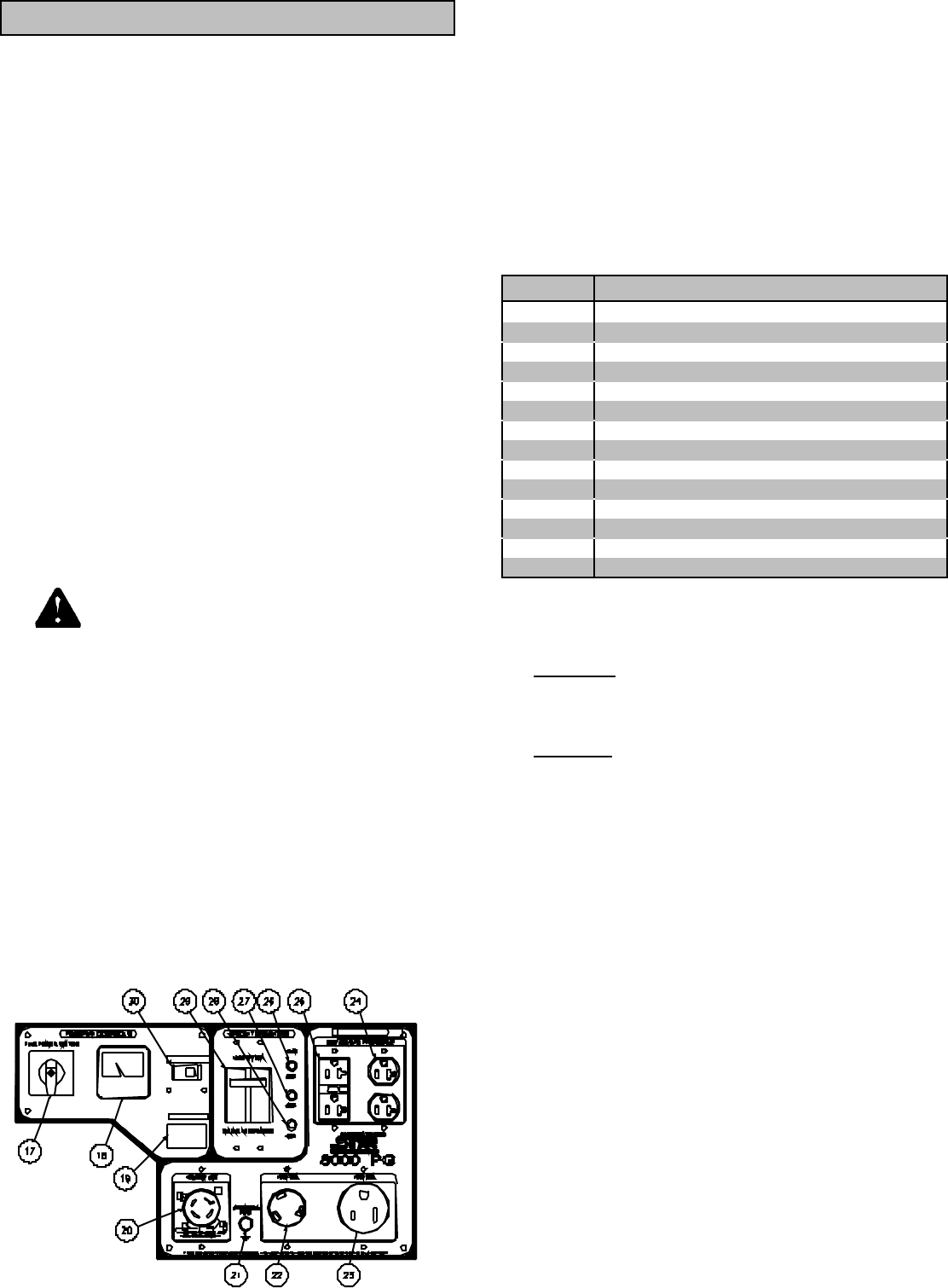
CONTROL PANEL IDENTI FICATION
Figure 3 (Ref. 17-30)
01937
Ref. Description
17 Full Power Switch
18 Voltmeter
19 Hour Meter
20 120V/240V-30A Twist-lock Receptacle
21 Grounding Post
22 120V-30A Twist-lock Receptacle
23 120V-50A Straight Blade Receptacle
24 120V-20A Duplex Receptacle
25 120V-20A GFCI Duplex Receptacles
26 20A Circuit Breaker
27 30A Circuit Breaker
28 50A Circuit Breaker
29 Main Line Circuit Breaker 30A
30 Idle Control On/Off Switch
Reference 17 - Full Power Switch. The switch
reconnects the two generator windings from parallel (120V
only) to series (120/240V).
• 120V Only: Allows all 6600 watts (55A) to be used in
any combination of 120 volt receptacles. The
120/240V 30A twist-lock receptacle is 120V only at this
time.
• 120/240V : Allows all 6600 watts to be used for 240V.
However, only half the power or 3300 watts (27.5A),
can be used at any one 120V receptacle. 120V output
can total 6600 watts.
Reference 18 - Voltmeter. Voltmeter needle should
be in green area during all generator load conditions.
Reference 19 - Hour Meter. Allows for better
maintenance scheduling of generator.
Reference 20 - 120/240V 30A Receptacle. This
receptacle is a NEMA L14-30P twist-lock device, and is
capable of drawing 30 amps. This receptacle accepts only
NEMA L14-30P plugs. Use this receptacle if installing a
transfer switch.
Reference 21 - Grounding Post. Ground the
generator via the grounding post, to a copper pipe or rod
that is driven down until it reaching moist soil.
References 22-25 - 120V Receptacles. The
generator has a control panel with:
• Reference 22 - One NEMA L5-30R twist-lock
receptacle, capable of drawing 30 amps. This
receptacle accepts a NEMA L5-30P plug.
RECE PT ACLES
H
@
H
?
G
HO UR METER
IDLE CONTR OL