


MAINTENANCE
28
F-030721L
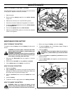
HOW TO LEVEL THE MOWER HOUSING
If the mower housing is level, the blade will cut easier and the lawn
will look better.
WARNING: Before you make an inspection, adjust-
ment, or repair to the unit, disconnect the wire to the
spark plug. Remove the spark plug wire to prevent
the engine from starting by accident.
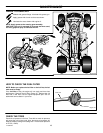
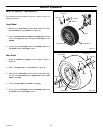
1. Make sure the unit is on a hard flat surface.
2. Check the air pressure in the tires. If the air pressure is incor-
rect, the mower housing will not cut level. Make sure the tires
are inflated to 14 PSI. (1 BAR).
IMPORTANT: On models equipped with gauge wheels, the
gauge wheels must be removed to correctly adjust the
level of the mower housing.
3. Some models have gauge wheels on the mower housing. If
equipped, remove the gauge wheels.
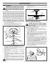
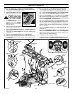
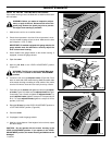
4. Open the cover.
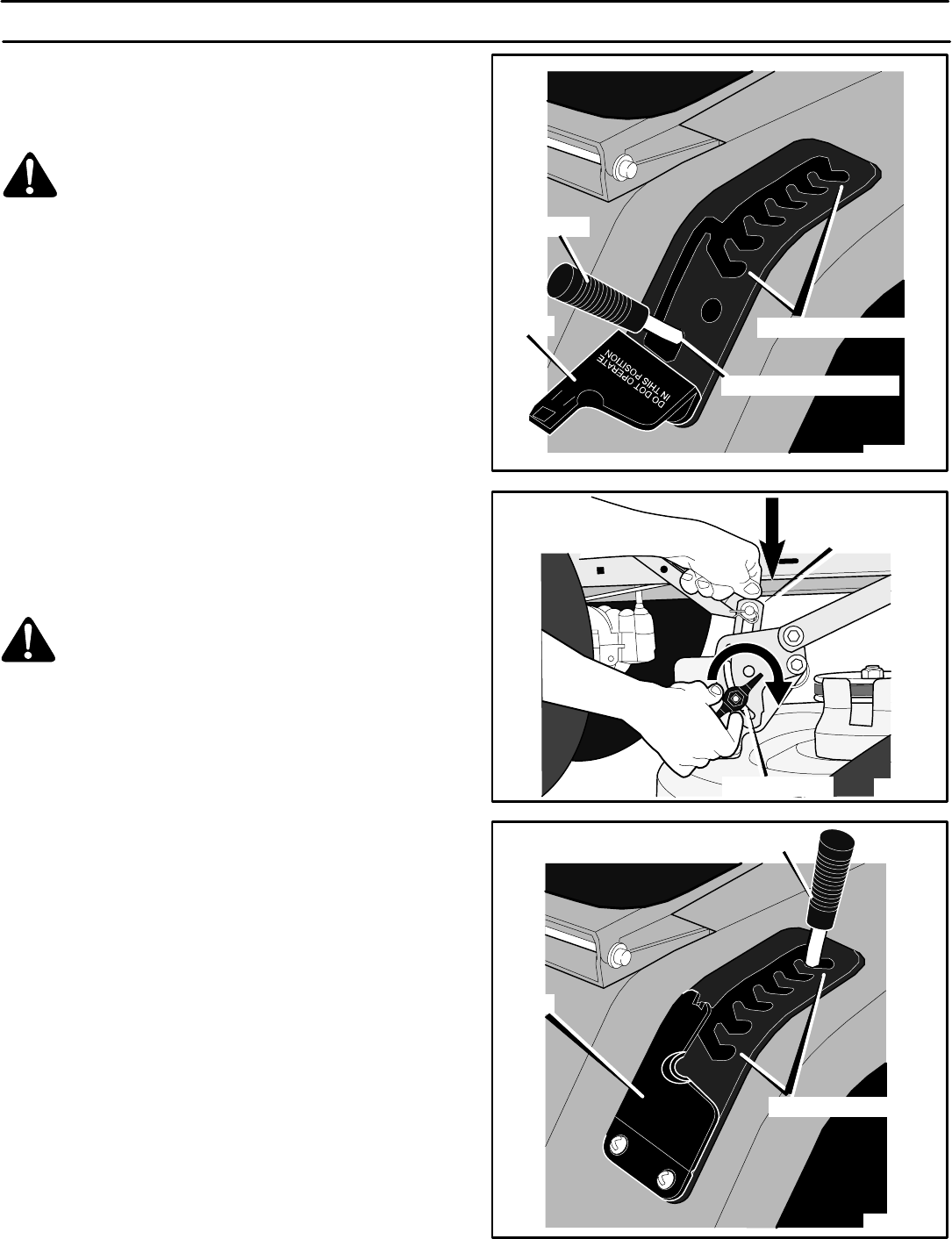
5. Move the lift lever to the LEVEL ADJUSTMENT position
(Figure 27).
WARNING: The lift lever is spring loaded. Make sure
the lift lever is locked in the LEVEL ADJUSTMENT
position.
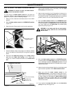
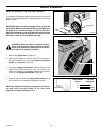
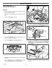
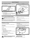
6. Loosen the left and right adjuster knobs (Figure 28). Push
down on each side of the mower housing. Make sure both sides
of the mower housing are setting on a flat surface. Also, make
sure the lift links are loose and can easily move up or down.
7. Push down on the lift links and tighten the left and right adjust-
er knobs (Figure 28). Make sure the adjuster knobs are tight.
If necessary, use a wrench to tighten the adjuster knobs. For
plastic adjuster knobs, tighten to a torque of 7 foot pounds (9,5
N-m). For metal adjuster knobs, tighten to a torque of 10 foot
pounds (13,5 N-m).
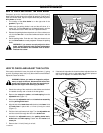
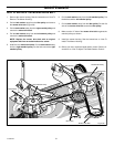
8. Raise the lift lever from the LEVEL ADJUSTMENT position to
a CUTTING HEIGHT position (Figure 29).
9. Close the cover.
10. If equipped, install the gauge wheels.
11. Mow for a short distance. If the height of cut is not level, repeat
the above steps.
CAUTION: Do not operate with the mower housing in the
LEVEL ADJUSTMENT position. If you operate in the LEVEL
ADJUSTMENT position, the mower housing and blades can be
damaged.
Figure 27
Level Adjustment Position
Cutting Height Positions
Cover
Lift Lever
Figure 28
Adjuster Knobs
Lift Link
Figure 29
Cutting Height Positions
Cover
Lift Lever