


PAGE 30 — TLG-12SPX4— OPERATION AND PARTS MANUAL — REV. #1 (12/17/09)
TLG-12SPX4 — GENERATOR START-UP PROCEDURE (MANUAL)
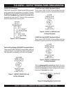
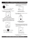
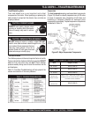
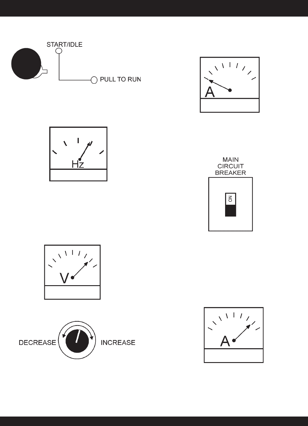
Figure 27. Voltage Adjust Control Knob
Figure 26. Voltmeter
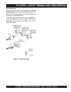
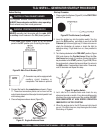
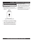
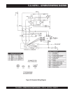
Figure 29. Main, GFCI, and Aux.
Circuit Breakers (ON)
7. Place the
main
(Figure 29) circuit breakers on the control
panel in the ON position.
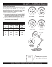
12. Observe the generator's ammeter (Figure 30) and verify
it reads the anticipated amount of current with respect
to the load. The ammeter will only display a current
reading if a load is in use.
Figure 30. Ammeter (Load)
13. The generator will run until manually stopped or an
abnormal condition occurs.
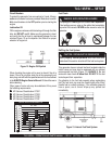
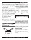
Figure 28. Ammeter (No Load)
8. The ammeter (Figure 28) will indicate
zero amps
with
no load applied. When a load is applied, the ammeter
will indicate the amount of current that the load is
drawing from the generator.
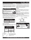
7. The generator's AC-voltmeter (Figure 26) displays the
output voltage in VOLTS. If the voltage is not within the
specified tolerance, use the voltage adjustment control
knob (Figure 27) to increase or decrease the desired
voltage.
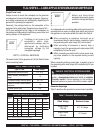
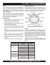
Figure 25. Frequency Meter (Hz)
6. The generator’s frequency meter (Figure 25) displays the
60 cycle output frequency in HERTZ.
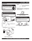
5. Pull the throttle lever (Figure 24) and turn to the right to
increase engine speed.
Figure 24.Throttle Lever (High Speed)