


PAGE 34 — MQ SP2 SLAB SAW — PARTS & OPERATION MANUAL — REV. #7 (09/08/06)
Drive V-Belt Check
The V-Belts of the SP2 slab saw have been factory set utilizing
precision standards. Operating the saw with less than the
specified number of V-belts (See Table 5), or belts that are
slipping
or are over-tensioned will significantly diminish the
performance of the saw, and may cause damage to the blade.
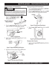
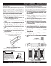
Drive V-Belt(s) Replacement & Tension Adjustments
Reference Pointers and Covers Assembly, Blade Shaft Assembly,
and Engine Mount Assembly for this operation.
1. Remove the
Belt Guard
(Pointers and Covers Assy., item
15), then loosen the tension of the V-Belts
2. Loosen the (4) 1-1/2” HHC screws (Engine Mount Assy.,
item 5).
3. Loosen and back-off the
Engine Mount Carriage Bolt
(Engine Mount Assy., item 1) from the frame to permit the
Engine Base Plate
(Engine Mount Assy., item 9) to pivot.
4. Pivot the Engine Base Plate to provide slack in the Drive V-
belts.
5. Remove/Replace the required V-belts (See Table 5).
6. Rotate the engine back into place and tighten the Engine
Mount Carriage Bolt.
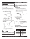
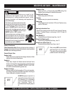
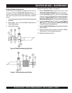
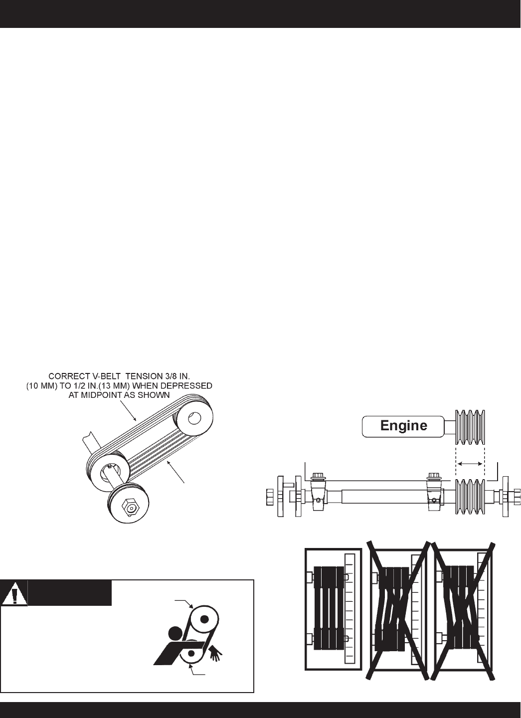
7. Adjust for the correct V-belt tension (See Figure 47).
MQ SP2 SLAB SAW — MAINTENANCE
Figure 47. V-Belt Adjustment/Tension
8. Retighten the (4) 1-1/2” HHC screws.
9. Replace all guards and covers.
Adjust V-Belt Alignment/Replacement Pulleys
The V-belts and their respective pulleys have been professionally
aligned at the factory. If there is a requirement to remove/replace
or adjust the pulleys, proceed with the following instructions.
1. Select the proper sized pulley both in outside diameter and
arbor size. Use approved parts to ensure the compo-
nent compatibility.
2. A change in Pulley diameters may require specifically sized
V-Belts. Contact Multiquip Service Department to en-
sure V-Belt compatibility.
3. Complete Drive V-Belt(s) Replacement steps (1 through 4)
3. Remove the V-Belts from around the Pulley(s).
4. Remove the set screws that secure the pulleys to the respec-
tive shafts (PTO shaft) for engine pulley or the (blade shaft)
for the blade shaft pulley.
5. Remove/replace the pulley by sliding it off the shaft.
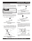
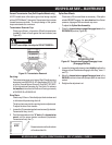
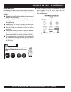
6. Reorient the new pulley on the shaft, and ensure precise
pulley alignment by utilizing an accurate straight edge (see
Figures 48 and 49).
7. Replace/tighten set screws treated with a drop of
LOCTITE
Threadlocker 266.
8. Orient the proper replacement V-Belt(s) around the blade
shaft pulley and engine pulley.
9. Reference steps 6-9 of the Drive V-Belt(s) Replacement
steps.
Figure 49. V-Belt Alignment
Figure 48. Pulley Alignment
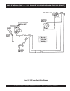
WARNINGWARNING
WARNINGWARNING
WARNING
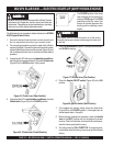
NEVER attempt to check the
V-belt with the engine running.
Severe injury can occur if your
hand gets caught between the
V-belt and the clutch. Always use
safety gloves.
CLUTCH
PULLEY
VIBRATOR
PULLEY