


SP1E16A PAVEMENT SAW • OPERATION MANUAL — REV. #0 (04/14/10) — PAGE 19
BLADES
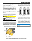
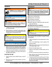
BLADE PLACEMENT
1. Blade Guard — Pivot the blade guard front cover all
the way back. The guard tension spring will keep the
front cover in position.
2. Blade Hex Nut — Unscrew the blade shaft nut (right
side loosens clockwise and tightens counter-clockwise
while the left side loosens counter-clockwise and
tightens clockwise. DO NOT overtighten the nut
(approximately 45-50 ft. lb/61-68 N/m) when finalizing
the assembly.
3. Outside Blade Flange (Collar) — Ensure that the
outside blade flange is placed flush against the
diamond blade. The inside surface of the flange must be
free of debris and permit a tight closure on the surface
of the blade core.
4. Diamond Blade — Ensure that the proper diamond
blade has been selected for the job. Pay close attention
to the directional arrows on the blade. The blade's
operating directional arrows must point in a "down-
cutting" direction to perform correctly. When placing
the blade onto the blade shaft, ensure the arbor hole
of the blade matches the diameter of the shaft.
5. Inner Flange (Collar) — This flange is fixed upon the
blade shaft. The inside surface of the flange must be
free of debris and permit a tight closure on the surface
of the blade.
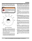
BLADE SPEED
A diamond blade’s performance is directly connected to
specific peripheral (rim) speeds.
The following shaft rotational speeds have been factory set
to ensure optimum blade performance.
SP1E16A 16-inch (406.4 mm) Capacity – 2,718 RPM
NOTICE
The following steps should be accomplished before
using the saw on any cutting surface.
WARNING
Dropping or forcing the blade onto the
cutting surface can severely damage the
diamond blade and may cause serious
damage to the saw and bodily harm.
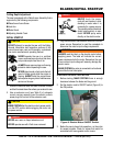
Blade Removal and Replacement
1. Set the motor ON/OFF switches to
the OFF position to prevent accidental
starting.
2. Place the saw on a stable level working
surface.
3. Ensure the blade is raised and the raise/lower crank
is locked into position.
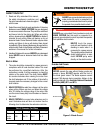
4. Lift up the blade guard cover to gain access to the
blade.
Figure 7. Mounting the Diamond Blade
5. Use the provided blade nut wrench to remove and
install the blade (Figure 7).
6. Unscrew the spindle nut (right side loosens clockwise
and tightens counter-clockwise while the left side
loosens counter-clockwise and tightens clockwise).
DO NOT overtighten the nut (approximately 45-50 ft.
lb/61-68 N/m) when finalizing the assembly.
CAUTION
ALWAYS ensure that unit is unplugged (disconnected)
when installing blade.
NOTICE
When removing or installing a diamond blade, please
note that the blade retaining nuts are left and right-hand
threaded.