


PAGE 38 —MQP20P STANDBY GENERATOR • OPERATION AND PARTS MANUAL — REV. #1 (11/28/11)
TROUBLESHOOTING (CONTROLLER)
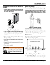
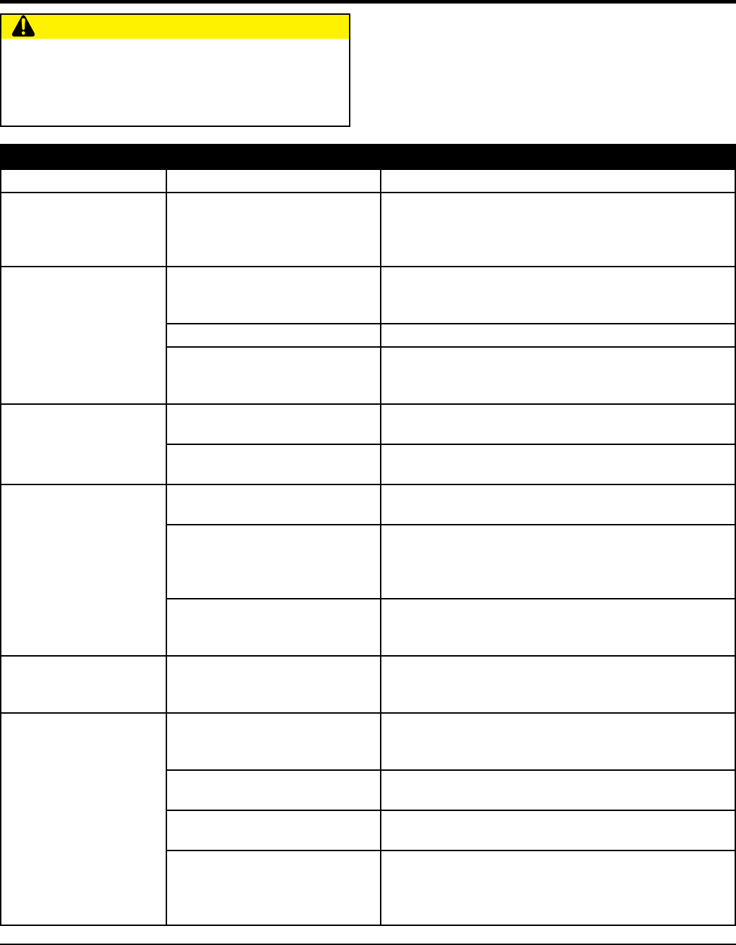
CAUTION
Before opening the enclosure to perform troubleshooting
or any service task, isolate the controller from any
possible source of power. Failure to do so may result in
serious personal injury or death due to electrical shock.
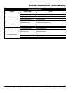
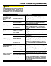
Troubleshooting (MEC20 Controller)
Symptom Possible Problem Solution
Does not power up even
with correct DC power
applied
Wiring errors or short circuit?
Check wiring and repair. NOTE: The MEC 20 electronic
fuse triggers when there is an overload condition and does
not reset until the supply voltage is removed and overload
condition is corrected.
LCD is not operational
Microprocessor defective?
Check that the "watchdog" LED on the rear of the PCB is
flashing red meaning that the microprocessor is working. If
not, repair or replace microprocessor.
Insufficient DC supply voltage? Check voltage at input terminals B+ and B- (10-30 VDC).
Bad LCD resolution?
Adjust LCD contrast potentiometer (R115) on the rear of
PCB for good pixel resolution for the operating temperature
of the unit.
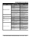
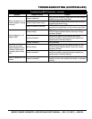
Controller cannot be
"reset"
Controller not in OFF mode?
Check that the controller is set to the OFF mode before
resetting.
Engine is running?
Check that the engine has come to a complete stop before
resetting.
No "RUN" output signal
Shutdown circuits reset?
Check that all shutdown circuits are reset (red shutdown
LED must be off).
No engine speed signal?
Engine speed signal must be detected (speed signal green
LED on) during cranking if the "run-output fail safe" feature
is enabled. Verify correct magnetic pick-up signal at cranking
(2.0 VAC min.)
RUN output LED off?
Check that the RUN output LED (on the rear of the PCB) is
on. If yes, verify relay contact operation on terminals #18 and
#19.
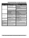
Overspeed shutdown occurs
at normal speed
Controller not correctly programmed?
Verify that the controller has been programmed with the correct
values for the number of flywheel teeth, nominal RPM, and
overspeed setpoint percentage.
Voltage or current metering
is reading incorrectly
Controller not correctly programmed?
Verify that the controller has been programmed with the correct
values for voltage sensing PT ratio and/or current sensing CT
ratio.
Battery not properly grounded?
Verify that the battery supply DC negative conductor is properly
grounded to the engine block (i.e. to a common ground point.)
Analog input not properly calibrated?
Verify that the controller's analog input has been properly
calibrated.
Incorrect wiring?
Verify that the voltage sensing wiring connection to the
controller matches power distribution type (Note: standard
direct voltage connection requires that the generator's neutral
is solidly grounded).