


PAGE 20 —MQP20P STANDBY GENERATOR • OPERATION AND PARTS MANUAL — REV. #1 (11/28/11)
DIGITAL CONTROLLER PANEL
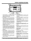
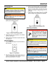
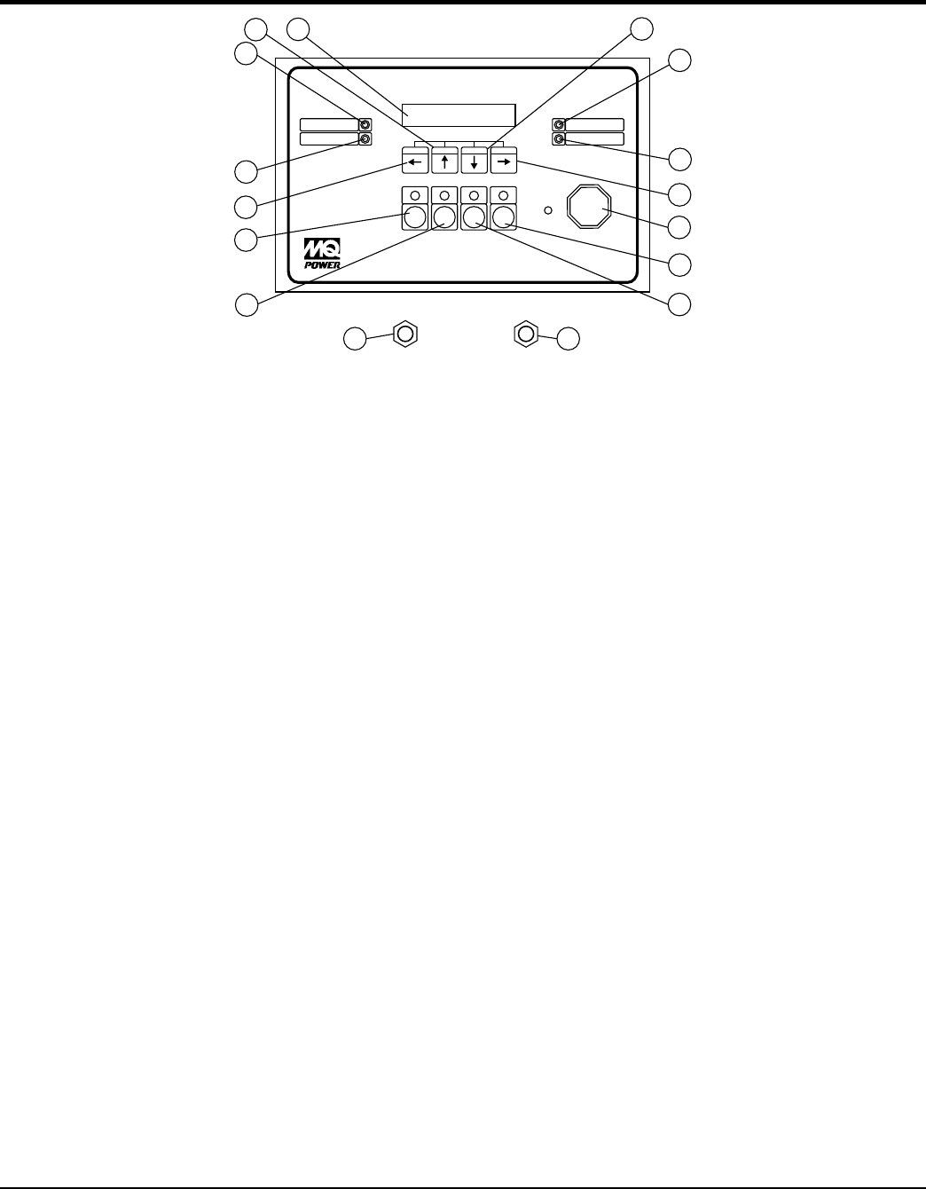
Figure 5. Digital Controller Components
RUN OFF
AUTO
LOAD
TEST
Vavg
600
Aavg
508
Freq
60.0
Microprocessor Engine Controller
MEC 20
ALARM
SHUTDOWN
EMERGENCY
STOP
READY
SPEEDSIGNAL
LAMPTEST
SILENCE
RESET
DECREMENT INCREMENT
EXIT
ENTER
1
13
14
2
3
6
8
9
10
11
4
5
12
7
FREQUENCY
ADJUST
VOLTAGE
ADJUST
15 16
1. Liquid Crystal Display — Displays voltage, amperage,
frequency,engine information, fault warnings, and other
generator and engine information.
2. EXIT Pushbutton — Press button to scroll backwards
through the status menus or programming prompts.
Press and hold for approximately 2 seconds to exit
programming menu when in the programming mode.
3. DECREMENT Pushbutton — Press button to change
a programming value while in the programming
mode. Press and hold this button to decrease value
continuously and release when desired value is
displayed. NOTE: The longer the button is held down,
the faster the value will decrease.
4. INCREMENT Pushbutton — Press button to change
a programming value while in the programming mode
or to select a desired programming menu loop. Press
and hold this button to increase value continuously and
release when desired value is displayed. NOTE: The
longer the button is held down, the faster the value
will increase.
5. ENTER Pushbutton — Press button to scroll through
the status menus or programming prompts. This
button is used to enter a programming mode as well
as accepting changed programming values. NOTE:
The longer the button is held down, the faster the next
menu prompt will appear.
6. RUN Pushbutton and LED — Press button to initiate
a manual start signal to the generator. The LED will
light when in RUN mode.
7. OFF Pushbutton and LED — Press button to initiate
a stop signal to the generator. The LED will light when
in OFF mode.
8. AUTO Pushbutton and LED — Press button to initiate
automatic operation of the generator. The LED will light
when in AUTO mode.
9. LOAD TEST Pushbutton and LED — Press button to
initiate load test of the generator when connected to
an associated transfer switch. The LED will light when
in LOAD TEST mode.
10. EMERGENCY STOP Pushbutton and LED — Press
button to initiate an emergency stop signal to the
generator.
11. READY LED — Lights when the generator is set for
automatic operation and no shutdown or alarm faults
have been activated.
12. SPEED SIGNAL LED — Lights when the engine speed
signal is detected.
13. ALARM LED — Lights when any pre-programmed
alarm fault has been activated.
14. SHUTDOWN LED — Flashes when any pre-
programmed shutdown fault has been activated.
15. FREQUENCY ADJUST — This screwdriver adjustable
potentiometer is used to fine tune the roll-off frequency
from 54 to 61 Hz.
16. VOLTAGE ADJUST — This screwdriver adjustable
potentiometer is used to fine tune the generator output
voltage.