


ga6HB/ga6HeB
Figure 4. Full Power Switch
120/240V
30A
0N
OFF
IDLE
CONTROL
OPERATION
SWITCH
ON
OFF
120
V
GA-6HB
120
20A
120
30A
AC CIRCUIT BREAKER
GFCI PROTECTED
120
AC VOLTMETER
120V
FULLPOWER
SWITCH
120V
120V/240V
MANUALRESET
P
O
W
E
R
F
A
U
L
T
120 V
20A
120 V
20A
IN SIMULTANEOUS USE 30AMP MAX
120/240V
30A
0N
OFF
IDLE
CONTROL
120
V
GA-6HEB
120
20A
120
30A
AC CIRCUIT BREAKER
GFCI PROTECTED
120
AC VOLTMETER
120V
FULLPOWER
SWITCH
120V
120V/240V
MANUALRESET
P
O
W
E
R
F
A
U
L
T
120 V
20A
120 V
20A
IN SIMULTANEOUS USE 30AMP MAX
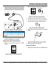
ELECTRIC START
START
SWITCH
OPERATION
SWITCH
15
15
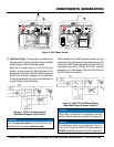
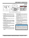
COMPONENTS (GENERATOR)
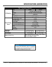
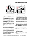
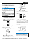
15. The generator is provided with a
full power switch. Figure 5 and Figure 6 show simplified
wiring diagrams of the dual voltage system.
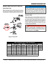
When the full power switch is in the 120 volt (up)
position, you can access the full rated power of the
generator at 120 volts from the GFCI duplex receptacle
and the120V twist-lock receptacle, or a combination
of both receptacles as long as the total load does not
exceed the generating set capacity.
Figure 5. 120V Full Power Switch
Simplified Diagram (Up Position)
NOTICE
When the full power switch is in the 120V position, the
240V twist-lock receptacle cannot be used..
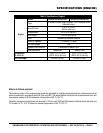
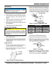
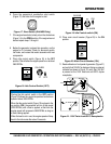
When the switch is in the 240 volt (down) position, you can
access half of the rated power of the generating set at 120
volts from the GFCI duplex receptacle and up to half of the
rated power of the set at 120 volts from 120V twist-lock
receptacle; or full rated power of the set at 240 volts from
the 240V twist-lock receptacle.
Figure 6. 240/120V Full Power Switch
Simplified Diagram (Down Position)
NOTICE
When using a combination of receptacles, total load
should not exceed the rated capacity of the generator.
NOTICE
In simultaneous mode use of receptaces, Figure 3,
items 3 and 10 (right most GFCI) is 30 amps maximum.
exceed 30 amps when using this configuration.