PAGE 28 — DCA-400SSV— OPERATION AND PARTS MANUAL — REV. #0 (04/19/06)
DCA-400SSV — GENERATOR OUTPUTS
Generator Amperage
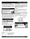
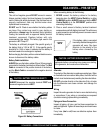
Tables 8 and 9 describe the generator’s current output capa-
bility for both 1Ø-phase and 3Ø phase applications.
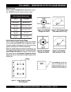
elbaliavAsegatloV.7elbaT
esahPeerhT
)elbahctiwS(
V802V022V042V614V044V084
esahPelgniS
)elbahctiwS(
V021V721V931V042V452V772
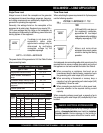
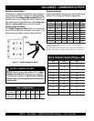
Generator Output Voltages
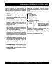
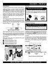
A wide range of voltages are available to supply voltage for
many different applications. Voltages are selected by apply-
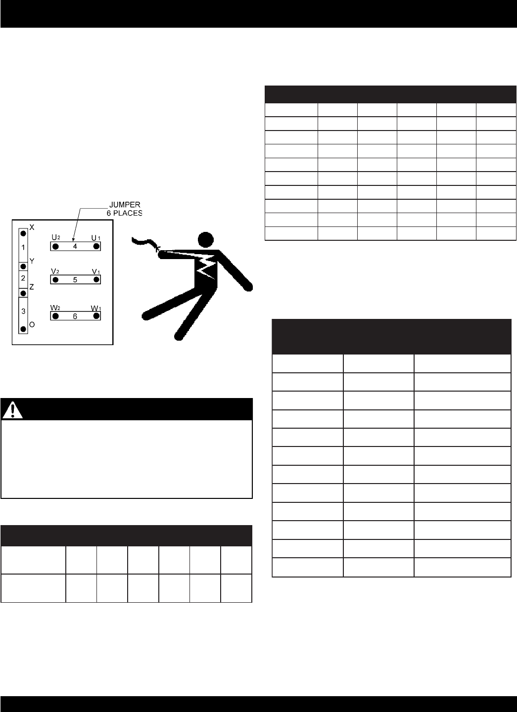
ing jumpers (6) to the
voltage change-over board
(Figure 14).
To obtain some of the voltages as listed in Table 6 (see
below) will require a fine adjustment using the
voltage regu-
lator
(VR)
control knob
located on the control panel.
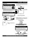
Voltage Change-Over Board
The
voltage change-over board
(Figure 14) is located on
the control box, behind the generator control panel. This
board has been provided for ease of voltage selection.
CAUTION - CHANGING VOLTAGES
NEVER attempt to place jumper plates on the
voltage
change-over board
while the generator is in operation.
There exist the possibility of
electrocution, electrical
shock or burn, which can cause severe bodily harm
or even death
!
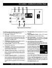
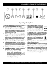
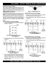
Figure 14. Voltage Change-Over Board
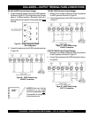
sgnitaRerepmArotareneG.8elbaT
⎯⎯
⎯
⎯⎯
1
∅∅
∅
∅∅
WkV021V931V042V772V084
082221911116955
01150336225113167
04188353349176179
071274704632302811
002555084772042831
032836155913572061
0622273261631130
81
092508596204743102
)xaM(023988767444383222
rotarenegehttnerrucfotnuomamumixamehttcelefersnoitaluclacesehT
rotare
neglatotehtniatbooT.riaplanimrettuptuohcaetaedivorpnac
.3ybylpitlumegarepma
spma684,1=3XriaplanimrettuptuorepV021@spma6.884:1elpmaxE
spma337=3XriaplanimrettuptuorepV042@spma3.442:2elpmaxE
sgnitaRerepmArotareneG.9elbaT
⎯⎯
⎯
⎯⎯
3
∅∅
∅
∅∅
AVKV042V084
001042021
031213651
061483291
091754822
022925462
052106003
082476733
013647373
043818904
073098544
004269184


