


PAGE 22 — DCA-400SSV— OPERATION AND PARTS MANUAL — REV. #0 (04/19/06)
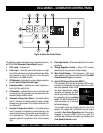
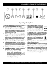
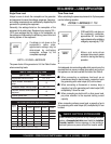
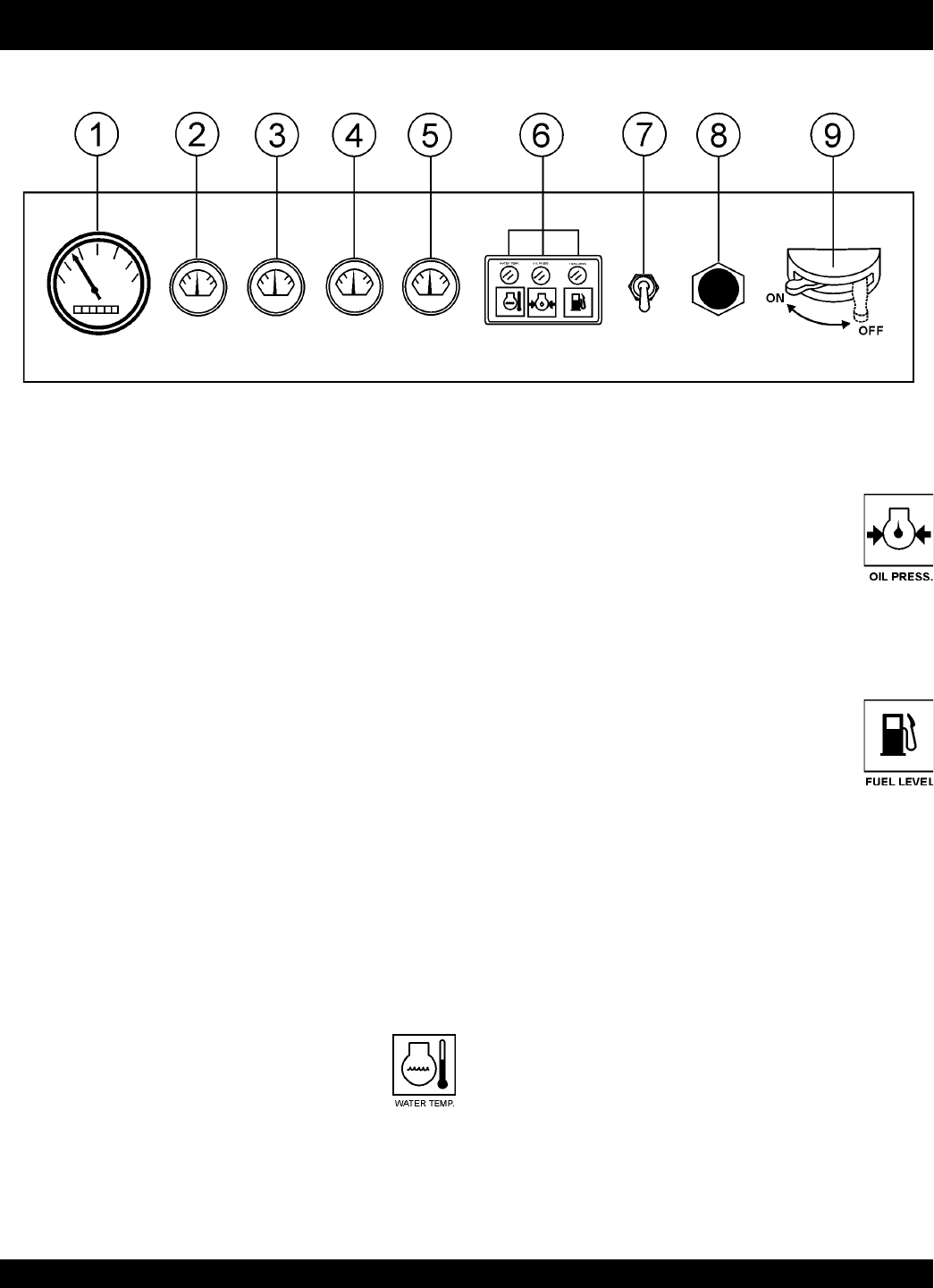
Figure 7. Engine Operating Panel
DCA-400SSV— ENGINE OPERATING PANEL
The definitions below describe the controls and functions of
the DCA-400SSV
Engine Operating Panel
(Figure 7).
1. Tachometer – Indicates engine speed in RPM’s for 60
Hz operation. This meter should indicate 1800 RPM’s
when the rated load is applied. In addition a built in hour
meter will record the number of operational hours that
the generator has been in use.
2. Oil Pressure Gauge – During normal operation this
gauge be should read between 44 to 73 psi. (303~503
kPa). When starting the generator the oil pressure may
read a little higher, but after the engine warms up the oil
pressure should return to the correct pressure range.
3. Water Temperature Gauge – During normal operation
this gauge be should read between 167° and 203°F.
4. Charging Ammeter Gauge – Indicates the current
being supplied by the engine’s alternator which provides
current for generator’s control circuits and battery
charging system.
5. Fuel Gauge - Indicates amount of diesel fuel available.
6. Engine Warning Lamps – There are three engine
warning lamps, they are defined as follows:
B. Low Oil Pressure Lamp – During normal
operation of the generator this lamp should
remain OFF. When the
Auto-OFF/Reset
-
Manual switch is set to the “Manual”
position to start the engine, the lamp will
be lit. After the oil pressure rises after start-
up the lamp will go OFF. If this lamp is ever lit (ON)
during normal operation of the generator, the emergency
shutdown device will stop the engine automatically.
C. Low Fuel Level Lamp – When this lamp is
ON, it is time to stop the engine and add
fuel. Remember to let the engine cool before
adding fuel.
7. Engine Speed Switch – This switch controls the
speed of the engine (low/high).
8. Emergency Stop Button – Push this button inward
to stop the engine in the event of an emergency. DO
NOT use this button as a means of stopping the engine.
9. Battery Switch – This switch should be set to the ON
position during normal operation. When the engine has
been stop, place this switch in the OFF position. DO
NOT turn this switch during normal operation, it could
cause damage to the electrical equipment.
A. Overheat Lamp – This lamp goes ON
when the cooling water temperature
rises abnormally. If the lamp goes ON
during normal operation of the generator,
the emergency shutdown device will
stop the engine automatically.